Edit Dimension Window
- General Overview
- Tips and Tricks
- Related Tools
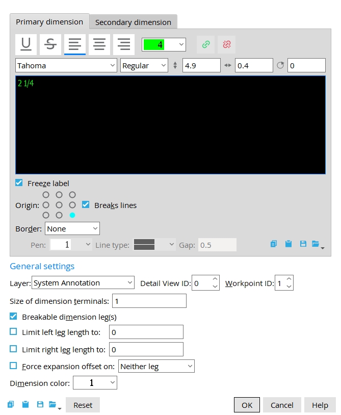
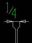
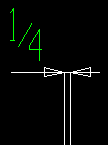
Primary dimension
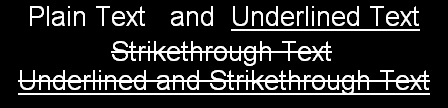
Underline: You can use this button to underline one or more words or letters in the Label text.
Strikethrough: You can use this button to strikethrough one or more words or letters in the Label text.
|
Justification: Left or Center or Right. Select one or more lines of text, then press the appropriate button to apply the justification that you want.
Each line in multi-line Label text can have a different justification. Justification has no effect on dimension label text that consists of a single line since the bounding box is the length and maximum character height of that single line.
Pen: 1 or 2 or 3 or 4 or 5 or 6 or 7 . This only affects the dimension label , not the dimension lines or legs. The selected pen sets the on-screen display color of primary dimension labels.
|
|
Insert/Edit Hyperlink: You can select one or more words and create a hyperlink (using the icon) to a PDF within the project or an external URL. If the linked PDF is located in the same folder, the hyperlink will open the corresponding sheet or detail.
Remove Hyperlink: Select the word or characters containing the hyperlink, then select the icon to remove it.
Font family: Any font that is listed can be selected for the primary dimension Label text .
Note: The fonts listed here are the TrueType fonts installed on your Widows operating system.
Font style: The style (Bold, Bold Italic, Italic, or Regular) of the selected Font. Different fonts may have different styles available to them.
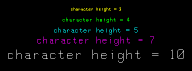
Font size: The height (in millimeters) that make up the dimension label. This value is independent of the Drawing scale of your current drawing.
|
Font aspect ratio: The width/height of the characters that make up the dimension label.
|
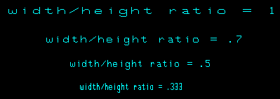
Note: A ratio of 0.6 renders the selected font at its native width. A ratio larger than 0.6 stretches the font, while a ratio less than 0.6 compacts the font.
Rotation (degrees): A positive or negative number of degrees (from -360 to 360). A positive number of degrees rotates the label counterclockwise, while a negative number of degrees rotates the label clockwise.
Label text: Entries should be in the Units set in Drawing Presentation for primary dimensions. Special characters can be added to the label. When you type label text that modifies or changes a calculated dimension, ![]() Freeze label is automatically checked, which prevents a dimension from being recalculated from its points.
Freeze label is automatically checked, which prevents a dimension from being recalculated from its points.
| Key Bindings for Text Entry (when the cursor is in the text-entry area) |
|
| key | action bound to key |
| Enter | creates a line break |
| Ctrl +a | selects all text |
| Ctr+Enter | executes OK |
| Ctr+c | copies selected text |
| Ctrl+x | cuts selected text |
| Ctrl+v | pastes cut or copied text |
| Tab | moves focus to next widget |
| Esc | executes Cancel |
Note: Lock manual editing of dimension text (Home > Project Settings > Fabricator > Detailing > Dimension Settings > General ) makes the text that is shown here non-editable. To override that setup choice, you can check the box for
Override Drawing Editor restriction options in the Drawing Data.
Freeze label: ![]() or
or ![]() . If this box
. If this box ![]() is checked, when you drag the leg of this dimension, the Label text of the dimension remains the same.
If the box
is checked, when you drag the leg of this dimension, the Label text of the dimension remains the same.
If the box ![]() is not checked, when you drag the leg of this dimension, the dimension updates to the new distance. If the Label text begins with a letter any dimensional component of that dimension will not be recalculated, even if Freeze label is not checked.
is not checked, when you drag the leg of this dimension, the dimension updates to the new distance. If the Label text begins with a letter any dimensional component of that dimension will not be recalculated, even if Freeze label is not checked.
Note: Freeze all dimension labels in the Drawing Data Panel prevents extension dimensions from be recalculated when you drag groups of objects. When
Origin: The selected location is highlighted blue and chooses an origin point for the dimension label.
The origin of a dimension label is highlighted along with the dimension label when the dimension label is selected.
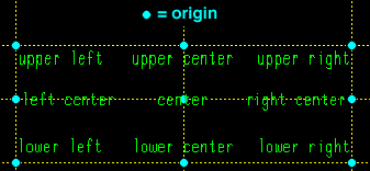
Tip: Instead of using Origin to reposition a dimension label, you can Shift -drag the dimension label to a new position.
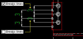
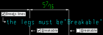
Breaks lines: ![]() or
or ![]() . If this box
. If this box ![]() is checked, this dimension label will break a line, polygon line, or a dimension leg where the label would intersect Break material lines at label interference or Break dimension lines at label interference must be checked for this option to apply.
If the box
is checked, this dimension label will break a line, polygon line, or a dimension leg where the label would intersect Break material lines at label interference or Break dimension lines at label interference must be checked for this option to apply.
If the box ![]() is not checked, the dimension label will not break any lines.
is not checked, the dimension label will not break any lines.
|
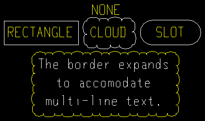
Border: None or Rectangle or Cloud or Slot .
|
Border pen: 1 or 2 or 3 or 4 or 5 or 6 or 7 .
![]()
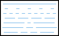
Border line type: The line type for the added boarder.
|
These line styles are equivalent to the dash patterns that you can select to be the Line type of a line. |
Border gap: A distance between the label and the boarder.
Secondary Dimension
Secondary Dimension: An additional dimension label that appears below the main (primary) dimension line on a drawing. It is typically used to show the same measured distance in an alternate unit. The same settings apply here as they do for the Primary Dimensions.
General Settings
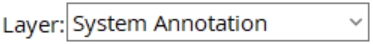
Layer: The drawing layer that the dimension you are adding or editing will be placed onto.
Detail View ID: The ID number of the Detail View this dimension is attached to.
Note: If the related detail view is removed, this dimension is also removed.
Workpoint ID: The ID number of the workpoint that the extension dimension is tied to.
Note: The leg of an extension dimension is drawn parallel to the workpoint origin symbol which that extension dimension is associated with. The distance reported in that extension dimension's label is the distance from that workpoint.
Size of dimension terminals: A number less than 1 reduces the size of a dimension's terminals. A number greater than 1 increases the size of a dimension's terminals.
Note: The Size of the dimension terminal entered here remains unchanged even if you change the Drawing scale.
Breakable dimension leg(s): ![]() or
or ![]() .
If this box
.
If this box ![]() is checked the leg(s) of this dimension are broken where they cross a label or dimension label.
If the box
is checked the leg(s) of this dimension are broken where they cross a label or dimension label.
If the box ![]() is not checked, the dimension leg(s) are continuous through any labels or dimension labels it crosses.
is not checked, the dimension leg(s) are continuous through any labels or dimension labels it crosses.
Note: The setup option Break dimension lines at label interference must be checked for this option to apply.
|
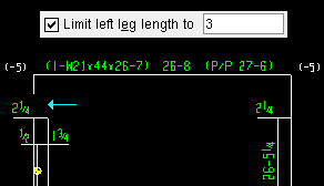
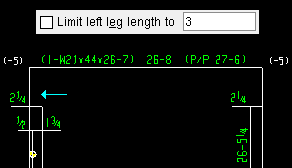
Limit left leg length to: If this box ![]() is checked, the entered distance will determine the maximum length of the leg. If the box
is checked, the entered distance will determine the maximum length of the leg. If the box ![]() is not checked, the left dimension leg is drawn to its end point .
is not checked, the left dimension leg is drawn to its end point .
|
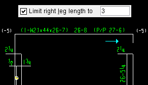
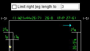
Limit right leg length to: If this box ![]() is checked, the entered distance will determine the maximum length of the leg. If the box
is checked, the entered distance will determine the maximum length of the leg. If the box ![]() is not checked, the left dimension leg is drawn to its end point .
is not checked, the left dimension leg is drawn to its end point .
|
Force expansion offset on: Left leg or Right leg or Both legs or Neither leg .
|
Dimension color: 1 or 2 or 3 or 4 or 5 or 6 or 7 . This only affects the dimension line and legs , not the label. The Dimension pen color in Drawing Presentation sets the color that is applied during detailing of members, submaterials, and erection views.
|
|
| The selected color sets the printing pen number (and on-screen display color) of the dimension lines. Line Weights assigns a printing thickness to each of the seven pens. |


|
|
OK (or the Enter key) closes this screen and applies the settings.
Cancel (or the Esc key) closes this screen without saving any changes.
Reset undoes all changes made to this screen since you first opened it. The screen remains open.

