"  Column Plate Welds " connection design locks
| Locks in " Column Plate Welds " do not affect base/cap plate piecemarks. They do affect column piecemarks. " Weld length is greater than maximum permissible on face " is a potential end connection failure message. |
|
|
||||||||||||
"
|
|
User Defined Connections: Settings that are locked (
) in a user defined connection file will automatically be locked on a member edit window for which that file is the " Input connection type ." You can, if you so choose, manually lock additional settings on the member edit window, and your changes will be retained, through multiple processes, so long as you do not change to a different connection then switch back to the original user defined connection.
Column Edit: To change a setting, first set it to locked (
) may be updated, and the "
Connection design locks :
![]() Column Plate Welds
Column Plate Welds
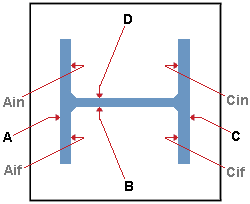
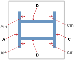
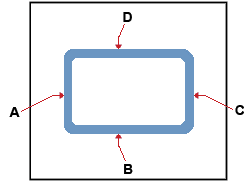
Location: Face A. . In the wide flange and welded plate box examples , this face is marked A and is the section's left flange. In the HSS rectangular example , this face is also marked A and is its left wall.
Location: Inner (FS) Face A. In the wide flange and welded plate box examples , this face is marked Aif and is the interior of the left flange, far side to the web. The program provides no option to weld the interior walls of an HSS rectangular or HSS round section or welded plate box section.
Location: Face B. In the wide flange and welded plate box examples , this face is marked B and is web near side. In the HSS rectangular example , this face is the section's near side wall and is marked B .
Location: Inner (FS) Face C. In the wide flange and welded plate box examples , this face is marked Cif and is the inside of the section's right flange, far side to the web. The program provides no option to weld the interior walls of an HSS rectangular or HSS round section or welded plate box section.
Location: Face C. In the wide flange example , this face is marked C and is the section's right flange. In the HSS rectangular example , this face is marked C and is its right wall.
Location Inner (NS) Face C. In the wide flange and welded plate box examples , this face is marked Cin and is the inside of the section's right flange, near side to the web. The program provides no option to weld the interior walls of an HSS rectangular or HSS round section or welded plate box section.
Location: Face D. In the wide flange and welded plate box examples , this face is marked D and is the far side of the web. In the HSS rectangular example , this face is marked D and is the far side wall.
Location: Inner (NS) Face A. The inside of Face A, near side to the web. In the wide flange and welded plate box examples , this face is marked Ain . The program provides no option to weld the interior walls of an HSS rectangular or HSS round section or welded plate box section.
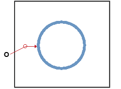
Location: All around. To get this location when the column " Section size " is an HSS rectangular (tube) and the connection is an auto base/cap plate, set " Weld pattern " to ' All around '. This location is the only location that is ever available when the column is an HSS round (pipe).
Weld type : Read only . The weld type is always ' Fillet '.
------ Common Settings ------
Weld type: None or Single Fillet or Single Bevel Groove or Solid Groove .
| symbol | name | weld used for ... |
|
|
fillet | General welding of material. |
|
|
bevel groove | General full penetration welding of material. |
|
|
square groove
|
Butt joints. |
' None ' removes the weld from the face.
' Single Fillet ' is available for all faces. Choosing ' Single Fillet ' for a particular face will cause the appropriate weld symbol to be drawn on the member detail.
' Single Bevel Groove ' is a selectable option for most faces. However, it is not available for the near side web (" Location: Face B ") or far side web (" Location: Face D ") of a wide flange, S shape, welded plate wide flange, etc.
' Solid Groove ' is a selectable option for most faces when the " Input connection type " is a ' User base/cap plate. ' It adds square groove welds to HSS rectangular (tube) and wide flange columns. However, it cannot be used on some faces without failing the connection:
Inner flange of a wide flange, S shape, welded plate wide flange, etc.: If you lock (
Wide flange column web faces: If you lock (
Combining with other weld types: If you enter ' Solid Groove ', you cannot lock (
Weld size: The weld size for shop welding the column plate to the column. .
To remove weld, set the " Weld type ' to ' None '. Do not set the weld size to ' 0 '.
It is permissible to enter a weld size that is greater than the " Maximum weld size for non-strength connections " ( Weld Design Settings , Home > Project Settings > Job ).
Maximum weld length: A distance (in the primary dimension " Units " or other units ). This is the length of weld that you want to allow to be generated for a particular face. If you lock this field and make an entry that is too long for the face, the connection will fail with the message " Weld length is greater than maximum permissible on face ."
|
|
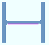

| The welds in these examples are magenta . The permissible length of a face is the distance from edge to edge, or, for a web, from k distance to k distance or, for the interior of a flange, from edge to k1 distance. Connection design centers a weld's length at the center of the face's permissible length. If the weld length is less than the permissible length of the face, the weld is centered with each of its ends set back equally. |
Permissible length: An unlocked (
Why maximum? Connection design will not add a weld that extends past the edge of a column plate. If you specify a " Maximum weld length " that would cause the weld to extend past the column plate, that weld will be cut at the edge of the column plate, resulting in its true length being less than the specified maximum. This may happen, for example, if the column plate is too small for the column or if it is improperly rotated.

