"  Column Plate " connection design locks
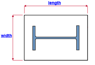
| These locks apply to a user base/cap plate on a column that does not frame to anything. Assuming that the " Plate rotation " is set to ' 0 ' (zero), " Plate length " is parallel with the column web. The " Column rotation " rotates the user base/cap plate along with the column. |
|
For user base/cap plates in column-to-beam or column-to-joist framing situations, see " |
|
||||||||
|
||||||||
|
||||||||
Connection Guide: Click here for related screen shots.
User Defined Connections: Settings that are locked (
) in a user defined connection file will automatically be locked on a member edit window for which that file is the " Input connection type ." You can, if you so choose, manually lock additional settings on the member edit window, and your changes will be retained, through multiple processes, so long as you do not change to a different connection then switch back to the original user defined connection.
Column Edit: To change a setting, first set it to locked (
). Related settings that are unlocked (
) may be updated, and the "
Left/Right end limit state " calculations will be updated. Settings that are locked (
) will not be changed by connection design , even if doing so might prevent a connection failure.
Connection design locks :
| Locks not dimensioned or called out on the drawing are marked ( not depicted ). |
![]() Column Plate
Column Plate
Plate dimensions (user base/cap plate, nothing framed to)
Plate length ( length ): Assuming the " Plate rotation " is ' 0 ' (zero) and the " Column rotation " is ' 0 ' and you are looking at the plate in a plan view, this is the distance from the left edge of the base/cap plate to the right edge of the base/cap plate. So long as the " Plate rotation " is ' 0 ', the length edges of the base/cap plate are parallel with the column web. See the example .
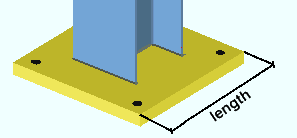
For a base/cap plate that does not frame to a beam or joist and whose " Plate rotation " is ' 0 ', " Plate length " is parallel with the column web. Plate width ( width ): Assuming the " Plate rotation " is set to ' 0 ' (zero), this is the length of either one of the two edges of the base/cap plate that are parallel with column flange as shown in cross section (see example ).
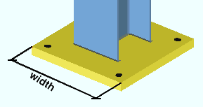
For a base/cap plate that does not frame to a beam or joist and whose " Plate rotation " is ' 0 ', " Plate width " is parallel with the column flanges. Plate thickness ( not depicted ): The " Material thickness " of the base/cap plate.
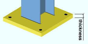
All bolts
Bolt diameter ( not depicted ): Generally it is best to keep this field unlocked (
) so that connection design will automatically enter the required bolt diameter for you.
diameter 
Hole diameter ( not depicted ): 0 (zero) or a hole diameter . 0 designates a CNC mark. When this field is unlocked (
), the hole diameter entered here is the Home > Project Settings > Job > Base/Cap Plate Schedule > " Hole Diameter ."
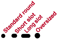
Hole type ( not depicted ): Standard round or Short slot or Oversized or Long slot or Anchor bolt hole or User slot #1 or User slot #2 or etc. Initially, when this field is unlocked (
), the hole type entered here is the Home > Project Settings > Job > Base/Cap Plate Schedule > " Hole Type ." On that setup window, anchor bolt holes, oversized holes and standard round holes are the only choices for hole type.
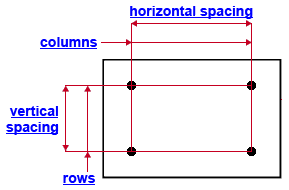
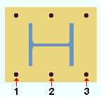
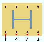
Columns: The quantity of hole columns. When the " Plate rotation " is ' 0 ', columns runs parallel with the column flanges. See the example .
3 columns of holes
4 columns of holes
Note: When there are an odd number of columns of holes (1, 3, 5, 7, etc.), the middle column is centered with respect to the length of the base / cap plate.
Horizontal spacing: The center-to-center distance between columns of holes. When the " Plate rotation " is ' 0 ' and the column does not frame to a beam or joist, this distance is measured parallel with the column web. Horizontal spacing is horizontal when the " Column rotation " is ' 0 ' and " Plate rotation " is ' 0 '. See the example .
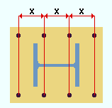
x = " Horizontal spacing " Rows: The quantity (0 or 1 or 2 or etc.) of hole rows. When the " Plate rotation " is ' 0 ', rows runs parallel with the column web. See the example .
2 rows of holes
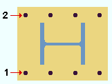
3 rows of holes
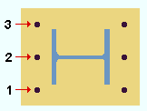
Note: When there are an odd number of rows of holes (1, 3, 5, 7, etc.), the middle row is centered with respect to the width of the base / cap plate.
Vertical spacing: The center-to-center distance between rows of holes. When the " Plate rotation " is ' 0 ' and the column does not frame to a beam or joist, this distance is measured parallel with the column flanges. Vertical spacing is vertical when the " Column rotation " is ' 0 ' and " Plate rotation " is ' 0 '. See the example .
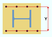
Y = " Vertical spacing "
