 Concrete Column ( Modeling > F2 >
  Concrete > select " Concrete Column" )
Tool summary :
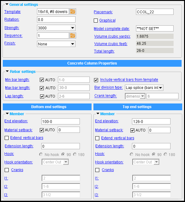
The Concrete Column Edit window :
|
To open this window :
- With the Default filter selected, double-click a concrete column member.
- Add a concrete column .
On this page :
Also see :
- Modeling (where a concrete column can be added or edited)
- Concrete column (definition)
- Concrete Setup > Column Templates (lists available concrete column templates)
- Column Template Editor (setup window for editing/reviewing an individual template)
- Tie Zone (may be added to a concrete column)
- Spiral Zone (may be added to a concrete column)
concrete | F2 > concrete / rebar > | concrete column | top
To add a concrete column :
|
Before adding a concrete column , you should confirm that the " Template " that you want to use for the column has been properly set up in Concrete Setup > Column Templates . The template sets, for example, whether the profile of the column is rectangular, square, round, or an irregular shape.
A concrete column can be added in Modeling by pressing F2 to open the Member Type Selection window, then double-clicking " Concrete Column ."
Only one work point is required to locate a column in a plan view . If that plan view is at the elevation you want for the bottom end of the column, then locating a point using INCL ( Intersection of Construction Lines ) will place the bottom end of the column at that elevation. A column added in this way is perfectly vertical.
Two work points are required to add a column in an elevation view. The order in which you locate these points does not matter since the work point located at lower elevation will always be recorded as the " Bottom end " work point.
On the Concrete Column Edit window, you must set a different " End elevation " for each end of the column. Also, the entering of a " Template " is required.
concrete | F2 > concrete / rebar > | concrete column | top
| Concrete column properties |
------  Rebar settings ------
Include vertical bars from template: ![]() or
or ![]() . This applies to concrete columns when dowels have been defined in the selected " Template " (from Concrete Setup > Column Templates ). This applies to the vertical reinforcing bars that run along the length of the concrete column. This does not apply to horizontal ties that are included in the template. Those ties can be added later, using the Tie Zone custom component.
. This applies to concrete columns when dowels have been defined in the selected " Template " (from Concrete Setup > Column Templates ). This applies to the vertical reinforcing bars that run along the length of the concrete column. This does not apply to horizontal ties that are included in the template. Those ties can be added later, using the Tie Zone custom component.
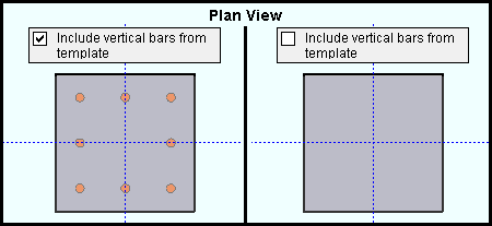
If this box is checked (
), vertical reinforcing bars (dowels) that are defined in the column " Template " are included in the concrete column. You also have options to enter a " Max bar length " and to " Extend dowels ." Ties -- optionally from the template -- can be added to the dowels using " Tie Zone ."
If the box is not checked (
), the rebar defined in the column template ( Column Templates ) is not included in the column. If you so choose, you can add a system of longitudinal and transverse reinforcing bars using Rebar System .
Max bar length: ![]() AUTO or
AUTO or ![]() AUTO . This applies when the option to "
AUTO . This applies when the option to " ![]() Include dowels from template " is checked.
Include dowels from template " is checked.
'
AUTO (checked) ' instructs the concrete column program to determine the " Max bar length ."
'
AUTO (not checked) ' lets you enter a distance in the primary dimension " Units " or other units .
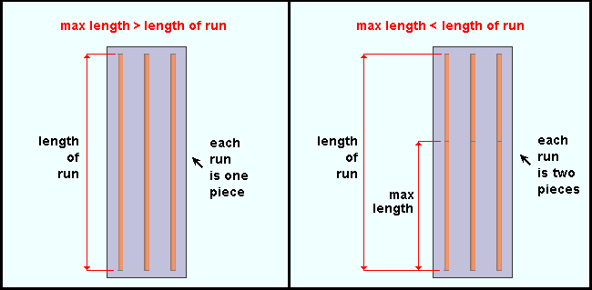
Max length >= length of run: If the " Max bar length " that is entered is greater than or approximately equal to the length of the rebar run, the rebar run will consist of a single rebar that is the required length. Assuming that there is no " Material setback ," that required length is the difference between the bottom- and top-end " End elevation " minus two times the " End cover " distance that is defined in the Concrete Column Template Editor .
Max length < length of run: If the " Max bar length " that is entered is less than the length of the rebar run and the concrete column program does not override your entry due to " Min bar length " being set to '
AUTO ', the rebar run is broken into two or more rebar lengths, the first of which is (or are) the " Max bar length ."
Example: " Max bar length " results in each rebar run in the concrete column being divided into three rebar segments. The first two segments are the " Max bar length ." The third segment is the length that is required to complete the run.
Min bar length: ![]() AUTO or
AUTO or ![]() AUTO .
AUTO .
'
AUTO (checked) ' instructs the concrete column program to determine the " Min bar length ." Be aware that when '
AUTO ' is checked, a distance that you enter for " Max bar length " may be overridden.
'
AUTO (not checked) ' lets you enter a distance in the primary dimension " Units " or other units . Be aware that this distance may not be applied when a specific " Max bar length " has been entered.
Lap length: ![]() AUTO or
AUTO or ![]() AUTO . This applies when the runs of longitudinal rebar have been dividend into multiple rebar lengths to accommodate the " Max bar length ." A lap splice is a common way of splicing two reinforcing bars. Lap splices that are within the same rebar run are modeled as a material clash between the two lengths of rebar that are being spliced. The length that the rebar clashes in the model is the " Lap length " that has been entered.
AUTO . This applies when the runs of longitudinal rebar have been dividend into multiple rebar lengths to accommodate the " Max bar length ." A lap splice is a common way of splicing two reinforcing bars. Lap splices that are within the same rebar run are modeled as a material clash between the two lengths of rebar that are being spliced. The length that the rebar clashes in the model is the " Lap length " that has been entered.
'
AUTO (checked) ' instructs the concrete column program to determine the " Lap length ."
'
AUTO (not checked) ' lets you enter a distance in the primary dimension " Units " or other units . That user-entered lap length applies when the " Max bar length " results in each run of vertical rebar being divided into multiple rebar lengths. The diagram below shows a single rebar run. Since rebar 2 requires two lap splices, the " Lap length " (marked lap in the diagram) is applied twice.

|
| Entering an appropriate " Lap length " ensures that sufficient lengths of rebar are ordered to achieve a lap splice. As shown in this diagram, a lap splice that is within the same rebar run is modeled as a material clash. |
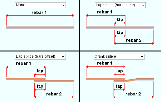
Bar division: None or Lap splice ( bars inline ) or Lap splice ( bars offset ) or Crank splice . These options determine if or how bars are spliced.
|
| Bar division options affect the length of rebar shape material. |
The ' None ' option prevents splices from being modeled. The rebar is modeled as a single length.
The ' Lap splice ( bars inline )' option models splices that accommodate the " Max bar length " and the " Overlap "; however, the splices are within the same rebar run and are modeled as clashing material.
The ' Lap splice ( bars offset )' option models splices that accommodate the " Max bar length " and the " Overlap ". The bars are offset so that their material does not clash.
The ' Crank splice ' option models splices that accommodate the " Max bar length " and the " Overlap ". The bars are within the same rebar run, but cranks are provided that conform to the " Crank length " options to prevent the bars from clashing.
Crank length: ratio or dimension . This option applies when " Bar division type " is ' Crank splice '.
' ratio ' specifies the ratio (expressed as a decimal number) of the crank length to bar size; that is, the crank length divided by the bar size. It follows that if you multiply the ratio by the bar size, you can calculate the resulting crank length:
Example using imperial units :
ratio = ' 6.0 '
bar size = #6 (i.e. 3/4", or 0.75 )
crank length = CC ÷ 0.75 = 6.0
C = 6.0 × 0.75
C = 4.5 , or 4 1/2"Example using metric units :
ratio = ' 6.0 '
bar size = #19 (i.e. 19 mm)
crank length = CC ÷ 19 = 6.0
C = 6.0 × 19
C = 114 mm' dimension ' specifies the crank length as a distance in the primary dimension " Units " or other units . This option allows the crank length to be entered directly.
concrete | F2 > concrete / rebar > | concrete column | top
|
|
|
------  Member ------
End elevation: The elevation (in the primary dimension " Units " or other units ) of the work point at this end of the concrete column.
|
|
|
Red-colored highlighting identifies an entry that is invalid. You need to change that setting, or you will not be able to close this window using " OK ." |
Warning : Both ends of a concrete column cannot have the same " End elevation ."If you added a concrete column by locating a single work point, the Z global coordinate of that work point is recorded as both the bottom-end " End elevation " and the top-end " End elevation ." You must change one or both of these entries, or the concrete column program will disable the " OK " button.
Changing an " End elevation " adjusts the length of the concrete column. This will be reflected in both its solids model and its member line after you press " OK ." When you re-open this window, the " Volume (yards) " and " Total length " of the column will be updated to reflect the " End elevation " change.
Extend vertical bars: ![]() or
or ![]() . This option is enabled when "
. This option is enabled when " ![]() Include dowels from template " is checked.
Include dowels from template " is checked.
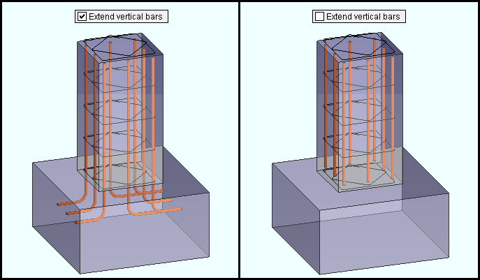
|
| This example shows the use of the " Extend dowels " option under " Bottom end settings ." That same option under " Top end settings " would extend the dowels above the top of the concrete column. |
If this box is checked (
) and an " Extension length " greater than ' 0 ' has been entered, vertical reinforcement bars (dowels) are extended that extension length distance beyond the end of the concrete column.
If the box is not checked (
), the vertical reinforcement bars extend only to the end cover of the concrete column.
Extension length: A distance (in the primary dimension " Units " or other units ). This option applies when the option to " ![]() Extend dowels " is checked.
Extend dowels " is checked.
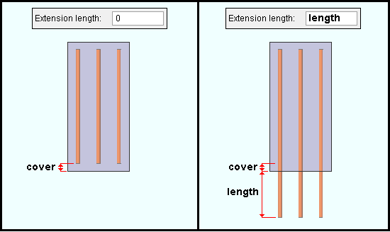
|
| This example shows the entering of an " Extension length " for " Bottom end settings ." That same entry under " Top end settings " would extend the dowels above the top of the concrete column. |
An extension length of ' 0 ' does not extend the vertical reinforcement bars (dowels). The reinforcement bars extend only to the end cover of the concrete column, which is the same result that you would get if you were to uncheck the box for "
Extend dowels ."
An extension length ' greater than 0 ' extends the vertical reinforcement bars that distance past the end of the concrete column.
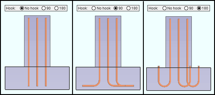
' No hook ' results in a straight rebar end.
' 90 ' results in a 90 degree hook at the end of the rebar.
' 180 ' results in a 180 degree hook at the end of the rebar.
Hook orientation: Up or down or Left or Right or Center In or Center Out or Horz. In or Horz. out or Vert. In or Vert. Out . This option applies when the Hook is ' 90 ' or ' 180 '.
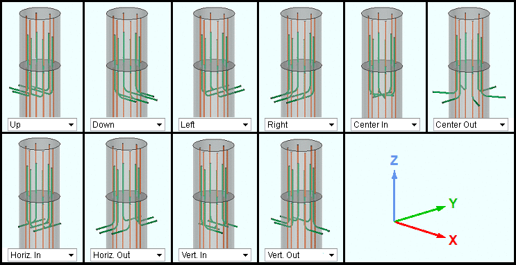
|
| " Hook orientation " options. In this example, a concrete column is shown whose column dowels lack cranks . The pictured UCS icon shows the relation of each orientation to the model's X, Y, and Z coordinates when the column " Rotation " is ' 0 ' degrees. |
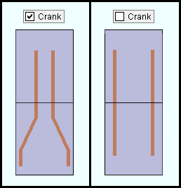
|
If this box is checked (
), vertical reinforcement bars (dowels) are extended bent.
If this box is not checked (
), vertical reinforcement bars (dowels) are extended straight.
l1, l2, and l3: A distance (in the primary dimension " Units " or other units ) for each segment of the crank. These options apply when " Crank " is checked ( ![]() ).
).
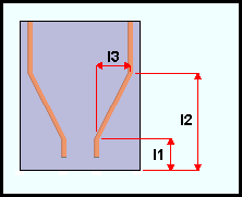
|
" l1 " and " l2 " and " l3 " are separate options. |
Tip: The dimension entered for " l2 " must be greater than the length of " l1 ".
concrete | F2 > concrete / rebar > | concrete column | top


