 Add Rebar System ( Modeling )
- On the Rebar System Edit window, look at the layer diagram. The layer diagram shows a section view of a wall and a plan view of a slab or footing in which a rebar system has been placed.
|
|
- To begin adding the component, you can click the Add Rebar System icon or use Add Component . The icon can be found in the command group ' Model--Component ' for the Ribbon Editor.
- See, on this page, to add, delete, or edit a rebar system .
Also see :
- Modeling (where custom components can be added)
- Custom components (topic)
- Copy Component (to copy the component to another concrete slab, wall, CMU wall, or pad footing)
- Move Component (to move the component to another concrete slab, wall, CMU wall, or pad footing)
- Explode Component (to reduce the component to its constituent materials and welds)
- Component Selection Tool (to search for custom components of a selected type)
- Model Tree (to find custom components and select them for deletion, editing, etc.)
- Rebar Area Layout (like Rebar System , but gives you rebar mat coverage in a layout specified by locating points)
To add the Rebar System custom component :
|
|
|
A Rebar System custom component can be added to concrete slabs , concrete walls , elevation walls , CMU walls and pad footings . The rebar system becomes a component of the member to which it was added.
To add the custom component : 1 ) In Modeling , select an appropriate concrete member. 2 ) Choose Model > Component > Add . 3 ) On the custom component selection list, choose " Rebar System " as the custom component you want to add. 4 ) If you are adding the rebar system to a slab, locate a reference point for the rebar system. 5 ) If prompted, locate a direction point. The angle of the line between your reference point and the point you select will determine the direction of the rebar grid. 6 ) The Rebar System Edit window opens. Enter the settings that you want, then press " OK " to close the window. 7 ) If User and Site Options > Modeling > " Automatically process after modeling operation " is set to ' Process and create solids ', the bars will be generated immediately. If not, the bars will be generated in the member the next time the member undergoes Process and Create Solids .
Tip: If you use in-tool selection -- that is, select the member after selecting " Rebar System " as the custom component you want to add -- only concrete and CMU walls, elevations walls, concrete slabs, and pad footings will be selectable. To delete a Rebar System custom component: 1 ) Use the Component Selection Tool and select the component in the slab, footing, or wall. Or , select the component in the Model Tree . 2 ) Press the Delete key (or choose Edit > Delete ). 3 ) Process and Create Solids iff User and Site Options > Modeling > " Automatically process after modeling operation " is not set to a choice that makes create solids take place automatically.
In the Model Tree , the Rebar System custom component is listed as Rebar System @ ( [ x, y, z ] ) when " View By " is set to ' Member piecemark ' or ' Member number '. The Rebar System component is listed under its member, after that member's connection components ( Left End and Right End ), and before that member's submaterials.
To edit a Rebar System custom component or review its settings, you can find the member it is added to and open its edit window. The component's settings will be contained in that window in a section named [ Rebar System ] . To edit a Rebar System custom component without opening a member edit window, use the Model Tree . You also can use the Selection Filter toolbar item to select the ' Custom Components ' filter and double-click any bar in the rebar system to edit the system. The Component Selection Tool can also be used to edit (and find) custom components.
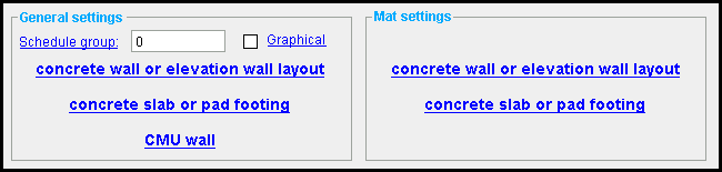
![]() Concrete slabs, concrete walls, elevation walls, CMU walls and pad footings :
Concrete slabs, concrete walls, elevation walls, CMU walls and pad footings :
------  General settings ------
|
A Rebar System component is automatically set to "
Graphical " whenever you make graphical changes to any of its bars. For example, when you Edit Material or apply the Extend Rebar Ends tool on one of the bars. This stops the component from being changed during Process and Create Solids . Click here for more information.
Instead of allowing the component to be made "
Schedule group: Any non-negative integer with less than ten digits. Your choice of schedule group is not limited by any configuration option. The group applies to this member only -- see special case below.
Reason to assign a schedule group: The output of the Rebar List Report , Rebar in Member Report , and Bend Schedule custom reports can be limited to particular schedule groups. As a result, you can assign rebar shape material to different schedules, and create separate reports for rebar from each schedule.
A special case: You change the schedule group on one of the rebar shapes. If you press " Yes " when prompted " Do you want regenerate... ," the changed schedule group is applied to ALL rebar matching the options checked in the Change All Options window.
User configuration: You can open the Report Manager window or the Table Edit window to copy, create, or edit rebar custom reports. " Edit " the report to add a comma-delimited list of schedule groups that the custom report will select.
Settings concrete slabs, concrete walls, elevation walls, and pad footings :
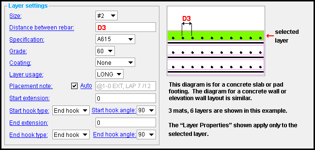
------ Layer settings ------
Size: A size designation that has been entered to the Rebar Definitions Setup window under the " Active rebar standard ".
Distance between rebar: The on center distance (in the primary dimension " Units " or other units ) between rebar of that layer.
Specification: A615 or A706 or etc. This is an ASTM specification entered into the Rebar Specifications window.
Grade: 60 or 40 or etc. This is the yield strength (grade) of the rebar.
The grade choices in this list box are limited to those entered in the Rebar Specification window for the " Specification " chosen for this rebar.
Coating: None or a Coating designation that is available in the " Standard " that you have selected.
The coating choices in this list box are limited to those entered in the Rebar Specification window for the " Specification " chosen for this rebar shape.
Select ' None ' if you do not want a coating. Since it is possible to create specifications that do not have coatings, it is possible that ' None ' may be your only option.
User configuration: If a coating is not available for selection, selecting a different " Specification " will make that coating available if the coating you want is in that other standard. If you don't want to change to a different " Specification ," you can open the Rebar Specifications window and add the coating you want to the specification that you currently have selected.
Layer usage: Blank or a usage description . The " Layer usage " that you enter here is used on the schedules that appear on drawings.
The usage descriptions in this field are limited to those entered in the Rebar Usage Descriptions window for the member category (e.g., ' Wall ', ' Pad Footing / Slab ', etc.) on which this component is placed.
User configuration: To add a " Layer usage " that you can select here, type the function to a blank line in the member category (e.g., ' Wall ', ' Pad Footing / Slab ', etc.) of the Rebar Usage Descriptions window.
Placement note: Auto or a string . This option is available for rebar systems placed in concrete walls or elevation walls. The " Placement note " can appear in reports made with Report Writer .
'
'
Auto (not checked) ' lets you enter your own ' string ' for the " Placement note ."
Start extension: The distance (in the primary dimension " Units " or other units ) that the start (i.e., the left end) of the rebar extends beyond the " Cover ."
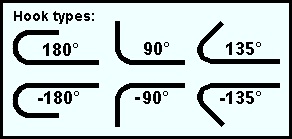
Start hook type: None or End hook or Stirrup hook or Seismic stirrup hook . This is the type of hook, if any, that appears at the left end of the rebar shape material. The " Hook type " chosen here determines which choices are available for the " Start hook angle " setting.
|
Hook
type |
Available angles |
| None | — |
| End hook | 90, 180, -90, -180 |
| Stirrup hook | 90, 135, -90, -135 |
|
Seismic
stirrup hook |
135, -135 |
Start hook angle: None or 180 or 135 or 90 or -90 or -135 or -180 . This is the bend, if any, that appears at the left end of the rebar shape material. The entries available here are determined by the entry made to " Start hook type ". The only value available for seismic stirrups is (±) 135 .
End extension: The distance (in the primary dimension " Units " or other units ) that the right end of the rebar extends beyond the " Cover ."
End hook type: None or End hook or Stirrup Hook or Seismic Hook . This is the type of hook, if any, that appears at the right end of the rebar shape material. The " End hook type " chosen here determines which choices are available for the " End hook angle " setting.
|
Hook
type |
Available angles |
| None | — |
| End hook | 90, 180, -90, -180 |
| Stirrup hook | 90, 135, -90, -135 |
|
Seismic
stirrup hook |
135, -135 |
End hook angle: None or 180 or 135 or 90 or -90 or -135 or -180 . This is the bend, if any, that appears at the right end of the rebar shape material. The entries available here are determined by the entry chosen for " End hook type ". The only entry available for seismic stirrups is (±) 135 .
Settings for concrete walls or elevation wall layouts :
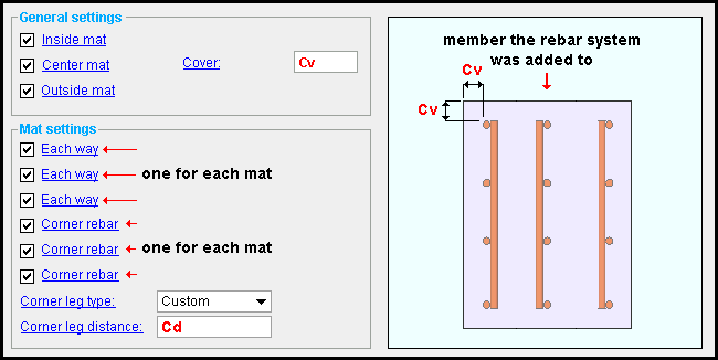
Outside mat: ![]() or
or ![]() .
.
Yo u can check one or more of these options. Depending on how many options you choose, a set of up to three rebar mats will be designed. These options the location of the rebar, relative to orientation of the wall that you chose when you placed the component. The names of these options accurately describe the location of the mats when the wall's layout points were placed clockwise.
If Inside is checked (
If Center is checked (
If Outside is checked (
Note: You can uncheck (
Cover: The distance (in the primary dimension " Units " or other units ) from the ends of the rebar to the edges of the wall.
------ Mat settings ------
If ' Each way ' is checked (
If ' Each way ' is not checked (
If ' Corner rebar ' is checked (
If ' Corner rebar ' is not checked (
Corner leg type: ' Custom ' or ' Overlap ' .
If the leg type is ' Custom ' , corner rebar overlaps the adjacent mats on each side by the distance you enter for the " Corner leg distance ."
If the leg type is ' Overlap ' , the distance by which the rebar extends from the corner is determined by the " Horz. in concrete " distance entered in the Reinforcing Bar Definitions window.
Corner leg distance: The distance (in the primary dimension " Units " or other units ) by which the corner rebar extends from the corner, when the " Corner leg type " is ' Custom '.
Settings for concrete slabs or pad footings :
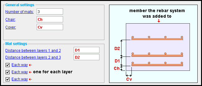
Number of mats: The number of grids. Each grid consists of a main bar layer, and -- when " Each way " is checked -- a secondary bar layer.
Chair: The distance (in the primary dimension " Units " or other units ) between the bottom layer of the lowest mat and the bottom of the concrete member.
Cover: The distance (in the primary dimension " Units " or other units ) from the ends of the rebar to the edges of the concrete member.
------ Mat settings ------
Distance between mats 1 and 2: The on center distance (in the primary dimension " Units " or other units ) between mats. This applies the " Number of mats " is greater than one. Another " Distance between mats ..." option is added for each mat. (For example, " ...between mats 2 and 3 ," " ...between mats 3 and 4 ," etc.)
If ' Each way ' is checked (
If ' Each way ' is not checked (
Settings for CMU walls :
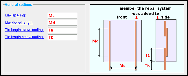
Max spacing: The distance (in the primary dimension " Units " or other units ) between vertical rebar. This is a maximum ; so the distance between one bar and its nearest bar may be significantly less.
Max dowel length: The length (in the primary dimension " Units " or other units ) of any single bar segment. Splices between segments are designed when each run has multiple dowels.
Tie length above footing: The distance (in the primary dimension " Units " or other units ) above the bottom of the CMU wall.
Tie length below footing: The distance (in the primary dimension " Units " or other units ) below the bottom of the CMU wall. The tie's extension below the footing depends on the setting made to this option, and not on the footing (if any) that is modeled below the wall.

