"  Gusset One Member " & " Brace Connection To Gusset Wide Flange Claw " & " Weld Conn2 "
| A claw angle gusset connection for a web-horizontal wide flange vertical brace to a column is designed per " |
|
||||
| " (gusset plate dimensions and location) 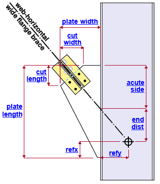 |
" (acute side and obtuse side cuts) 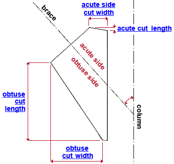 |
|||
| " (angle to gusset connection) 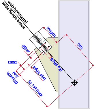 |
" (angle to brace connection) 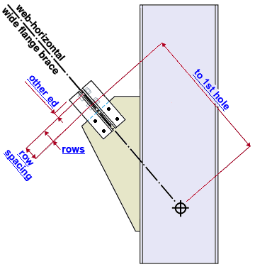 |
|||
|
" (" Gusset to supporting member " = ' Welded ') 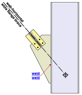 |
|
|||
Connection Guide: Click here .
User Defined Connections: Settings that are locked (
) in the user defined connection file will automatically be locked on the member edit window. You can, if you so choose, manually lock additional settings on the member edit window, and your changes will be retained, through multiple processes, so long as you do not change to a different connection then switch back to the original user defined connection.
Vertical Brace Edit: To change a setting, first set it to locked (
) may be updated, and the "
Connection design locks :
| Locks not dimensioned or called out on the drawing are marked ( not depicted ). |
![]() Gusset One Member
Gusset One Member
(web-horizontal wide flange vertical brace, claw angles, to a column)
Gusset plate dimensions and location
Plate thickness ( not depicted ): The " Material thickness " of the gusset plate.
Width ( plate width ): The distance (perpendicular to the work line of the supporting column) from the framing edge of the gusset plate (the edge that welds to the column in the example shown) to the farthest point on the same surface that is opposite to the framing edge of the gusset plate.
Length ( plate length ): The length of the framing edge of the gusset plate (which welds to the supporting column in the example shown). The gusset plate " Length " is measured parallel with the work line of the supporting column.
Refx: The positive (+) or negative (-) distance (parallel with the supporting column's work line ) from the work point for this end of the vertical brace to the corner of the framing edge of the gusset plate that this end of the vertical brace points toward (see example ). For a gusset plate to a perfectly vertical column, this distance is vertical. A " Refx " of ' 0 ' aligns the corner of the gusset plate with the work point and perpendicular to the column's work line. Entering a positive (+) distance moves the gusset plate parallel with the column's work line toward the opposite end of the vertical brace. Entering a negative (-) distance moves the corner of the gusset plate parallel with the column's work line in the direction that this end of the vertical brace points toward. Changing the " Refx " moves the plate, but not the holes on the plate.
Refy: The positive (+) or negative (-) distance (perpendicular to the supporting columns work line ) from the work point for this end of the vertical brace to the framing edge of the gusset plate (which welds to the column's flange in the example shown). For a gusset plate to a perfectly vertical column, this distance is horizontal. A " Refy " of ' 0 ' aligns the framing edge of the gusset plate with the work point and parallel to the column's work line. Entering a positive (+) distance moves the gusset plate perpendicular to the column's work line toward the opposite end of the vertical brace. Entering a negative (-) distance moves the gusset plate perpendicular to the column's work line in the direction that this end of the horizontal brace points toward. Changing the " Refy " moves the plate, but does not move the holes on the plate.
Connection cut width ( cut width ): The distance (perpendicular to the work line of the supporting column) between the two corners of the connection edge of the gusset plate. The connection edge is the edge that the web-horizontal wide flange vertical brace connects to with claw angles (see example ). This distance is not the actual length of the particular edge, but the length of that edge as measured parallel with the depth of the column.
Connection cut length ( cut length ): The length (as measured parallel with the work line of the supporting column) of the connection edge of the gusset plate. The connection edge is the edge that the web-horizontal wide flange vertical brace connects to with claw angles (see example ). This distance is not the actual length of the particular edge, but the length of that edge as measured parallel with the framing edge of the gusset plate.
Acute side clip cut width ( acute side cut width ): The distance (measured perpendicular to the work line of the column) between the two corners of the acute-side clip cut. As the example shows, the gusset plate is divided into an acute side and an obtuse side by the work line of the brace. The acute side of the gusset plate is the side contained by the acute angle between the brace and the column.
Acute side clip cut length ( acute cut length ): The distance (measured parallel with the work line of the column) between the two corners of the acute-side clip cut. As the example shows, the gusset plate is divided into an acute side and an obtuse side by the work line of the brace. The acute side of the gusset plate is the side contained by the acute angle between the brace and the column.
Obtuse side clip cut width ( obtuse cut width ): The distance (perpendicular to the work line of the supporting column) between the two corners of clip cut made to the obtuse side of the gusset plate. The obtuse side of the gusset plate is the side contained by the obtuse angle between the column and the brace. See the example .
Obtuse side clip cut length ( obtuse cut length ): The distance (parallel to the work line of the supporting column) between the two corners of the clip cut made to the obtuse side of the gusset plate. The obtuse side of the gusset plate is the side contained by the obtuse angle between the column and the brace. See the example .
Flat width ( not depicted ): The distance (perpendicular to the work line of the supporting column) that is the width of the cut that is made to the corner of the gusset plate that the work line of the brace points toward. In the example above, the " Flat width " cut is made to the corner of the gusset plate that is closest to the brace's work point.
End distance ( end dist ): The positive distance parallel with the framing edge of the gusset plate (the edge that fastens to the supporting column) from the point where the work line of the brace intersects the framing edge of the gusset plate to the corner of the framing edge that this end of the vertical brace points toward.
Length acute side ( acute side ): The distance (parallel to the work line of the supporting column) from the acute-side corner of the framing edge of the gusset plate to the work line of the brace. The framing edge has two corners. The acute-side corner is the corner of the framing edge that is interior to the acute angle formed by the work line of the brace to the work line of the column (see example ).
![]() Brace Connection To Gusset Wide Flange Claw
Brace Connection To Gusset Wide Flange Claw
(web-horizontal wide flange vertical brace, claw angles, to column)
Claw angle dimensions and location
Section size ( not depicted ): The section size of the four claw angles used to bolt the gusset plate to the wide flange vertical brace. For example, L4x3x5/16. The angle you enter here must exist in the local shape file, or validation will not accept your entry. To enter an angle section size, you can type in the section size that you want, or you can press the "file cabinet" browse button (
) and double-click a section size from the list of available angles in the local shape file .
Long leg to ( not depicted ): Supporting or Supported . ' Supporting ' field bolts the long leg of the angle to the gusset plate. ' Supported ' shop bolts the long leg of the angle to the web of the web-horizontal wide flange vertical brace.
Length: The distance (parallel with the work line of the vertical brace) between the edge of the angle that is closest to the work point for this end of the vertical brace and the edge of the angle that is closest to the work point for the opposite end of the vertical brace (see example ). This distance is the length that you want the selected " Section size " to be cut to. Assuming this field is unlocked (
Refx: The distance (parallel with the work line of the vertical brace) from the work point for this end of the vertical brace to the nearest edge of any one of the claw angles (see example ). All four of the claw angles are positioned this distance from the brace work point.
Refy ( not depicted ): The distance (perpendicular to the work line of the vertical brace) from the work line of the vertical brace to the heel of any one of the claw angles. This distance applies to all four of the claw angles. The distance is not shown in the example because the claw angles are very close to the work line of the brace.
Gage leg ( not depicted ): The distance (perpendicular to the work line of the vertical brace) from the heel of any one of the claw angles to the center of the column of holes for shop bolting that angle to the web of the vertical brace. This gage applies to all four of the claw angles.
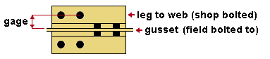
Gage osl; The distance (perpendicular to the work line of the vertical brace) from the heel of any one of the angles to the center of the column of holes for field bolting that angle to the gusset plate -- see example ). This gage will be applied to the outstanding legs of all four of the claw angles.
Angle to gusset connection ( field bolted )
Bolt diameter ( not depicted ): You can either type in any diameter (inches or mm), or you can select a bolt diameter from the combo box (
). The diameters that are listed in the combo box come from Home > Project Settings > Job > Bolt Settings > the " Available bolt diameters " list. The bolt diameter entered here together with the " Hole type " entered below set the diameter of holes through the gusset plate and the claw angles.
Hole type ( not depicted ): Standard round or Short slot or Oversized or Long slot or User slot #1 or User slot #2 . The hole type selected here, together with the " Bolt Diameter " entered above, set the diameter of holes for field bolting the claw angles to the gusset plate.

Rows: The total number of holes in any column of holes for bolting the claw angles to the vertical brace gusset plate -- see example . Bolt rows on a vertical brace gusset plate run parallel with the work line of the vertical brace. For the wide flange vertical brace shown in the example above, the number of " Rows " is ' 2 '.
Distance to 1st hole along brace ( to 1st hole ): The distance (parallel with the work line of the vertical brace) from the work point for this end of the vertical brace to the center of the nearest hole on the gusset plate (see example ).
Hole spacing along brace ( row spacing ): The distance (center to center) between of any two adjacent holes in the same column of holes for connecting the claw angle to the gusset plate (see example ).
End connection failure message: Invalid bolt spacing
Columns ( not depicted ): The number of columns of holes on the claw angle leg that bolts to the gusset plate. Columns of holes run perpendicular to the work line of the vertical brace. In the example above, the number of " Bolt columns " is ' 1 '. If the connection has only a single column of holes, you will not get this setting.
Hole spacing perpendicular to brace ( not depicted ): The distance (center to center) between any two columns of holes on the claw angle leg that bolts to the gusset plate. If there is only a single column of holes in the claw angle, you will not get this setting. Bolt column spacing runs perpendicular to the work line of the vertical brace.
Edge distance along brace ( edge dist ): The distance from the forward edge of the claw angle to the nearest hole for field bolting the angle to the gusset. This distance is measured along the work line of the vertical brace. The forward edge of the claw angle is the edge that is closest to the column.
Other edge distance along brace ( other ): The distance from the connection edge of the gusset to the nearest hole in the gusset. This distance is measured along the work line of the vertical brace.
Angle to brace connection ( shop bolted )
Bolt diameter ( not depicted ): You can either type in any diameter (inches or mm), or you can select a bolt diameter from the combo box (
Hole type ( not depicted ): Standard round or Short slot or Oversized or Long slot or User slot #1 or User slot #2 . The hole type selected here, together with the " Bolt Diameter " entered above, set the diameter of holes for shop bolting the claw angles to the web of the web-horizontal wide flange vertical brace.
Rows: The total number of holes in any column of holes for bolting the claw angles to the web of the web-horizontal wide flange vertical brace -- see example . Bolt rows on a vertical brace gusset plate run parallel with the work line of the vertical brace. For the wide flange vertical brace shown in the example above, the number of " Rows " is ' 2 '.
Distance to 1st hole along brace ( to 1st hole ): The distance (parallel with the work line of the vertical brace) from the work point for this end of the vertical brace to the center of the nearest hole on the web of the web-horizontal wide flange vertical brace (see example ).
Hole spacing along brace ( row spacing ): The distance (center to center) between of any two adjacent holes in the same column of holes for fastening the claw angles to the vertical brace web (see example ).
End connection failure message: Invalid bolt spacing
Columns ( not depicted ): The number of columns of holes on the claw angle leg that bolts to the web of the web-horizontal wide flange vertical brace. Columns of holes run perpendicular to the work line of the vertical brace. In the example above, the number of " Bolt columns " is ' 1 '. If the connection has only a single column of holes in the claw angle, you will not get this setting.
Hole spacing perpendicular to brace ( not depicted ): The distance (center to center) between any two columns of holes on the claw angle leg that bolts to the web of the web-horizontal wide flange vertical brace. If there is only a single column of holes in the claw angle, you will not get this setting. Bolt column spacing runs perpendicular to the work line of the vertical brace.
Edge distance along brace ( not depicted ): The distance back from the forward edge of the brace main material to the nearest hole in the brace's web for shop bolting the claw angle to the web. The forward edge of the brace is the edge closest to the brace's work point. This dimension is not shown in the example above because the brace's main material is not shown and therefore cannot be dimensioned to.
Other edge distance along brace ( other ed ): The distance from the edge of the claw angle to the nearest hole for shop bolting the angle to the web of the web-horizontal wide flange vertical brace.
![]() Weld Conn2
Weld Conn2
(web-horizontal wide flange vertical brace, claw angles, to a column)
Shop weld, gusset plate to the supporting column
Weld size ( weld ): The weld size for shop welding the gusset plate to the supporting column as in the example shown. You can optionally shop bolt the gusset to the column with a clip angle ("
To get a weld ("
To instead get a clip angle ("

