Connection Guide : Vertical Brace Connections
| Disclaimer: This guide is not comprehensive. It only shows some of the many vertical brace connections that connection design can create when ' Vbrc plate ' or ' Welded ' or ' Plain end ' is selected as the " Input connection type ." |
| Vertical Brace to Column with Base/Cap Plate | ||
| To column & auto cap plate | Web vertical wide flange, paddle plates | |
| To column & base plate | ||
| Vertical Brace Intersection Connections | ||
| To a wide flange vertical brace | Intersection plate ( leg-up ) | |
| Different brace material types | Single-side intersection plate | |
| Vertical Brace Shared K Connections | ||
| Two braces, shared gusset | Three braces, shared gusset | Also see : HSS Column Reinforcement Rod Bracing |
| Seismic 2-point | Different bolt diameters | |
Also see :
- Vertical Brace Edit (edit window)
- Connections, 'Vbrc plate' (help page)
- Connection design locks ( Beam Edit window)
- Connection design locks ("
 Leaf" names)
- Status Display ( Connection type > Vertical brace )
***No Framing Situation Required***
| Stitch Plates for a Vertical Brace with Plain Ends | |
|
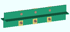
Section size: An angle section. |
| Input connection type: ' Plain End '. | |
| Settings: " Double material " in a ' Star ' configuration. To get three equally spaced spacers, you can set the " Max stitch plate spacing " or the " Number of stitch plates ." You can also get stitch plates on ' Back to back ' angles or channels. | |
|
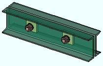
Here's an example of a double channel with stitch plates. Both ends of this channel are set to ' Plain End '. The member is displayed in solid transparent main so that you can see the bolted rectangular stitch plates. |
***Various Framing Situations***
| HSS Column Reinforcement for a Vertical Brace Gusset | |
| Connection Design Locks = " Column Reinf Plate " | |
|
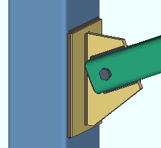
Section size: HSS / TS for column. Vertical brace can be any valid " Section size ." |
| Framing conditions: Brace to beam-column or brace to column only or 2 or 3 braces with shared gusset to a column. | |
|
Settings: " Use HSS column reinforcement plate " (' Yes ' or possibly ' Automatic '). |
|
| Fixes this failure message: " HSS wall strength fails ." | |
***Various Framing Situations***
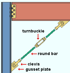
| Rod Bracing | |
| Connection Design Locks = " Brace Connection To Gusset " | |
| Vertical brace section size: round bar |
|
| Framing situations: Brace to beam or brace to column or brace to column and base/cap plate or brace to beam & column or 2-point or 3-point braces with shared gusset. | |
| Setup: " Tension Only Braces " in Member Detailing and Fabricator Options provides various setup options. The " Capacity " (nominal strength) of a clevis and turnbuckle is stored in the local shape file. Fu and Fy values at Home > Project Settings > Job > Turnbuckle / Clevis / Pin Grades are used by connection design. | |
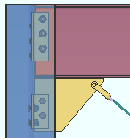
| Example 1: A rod brace in a beam & column framing situation, with the beam framed to a column web. " UFM special case design " is set to ' No special case ' under " |
|
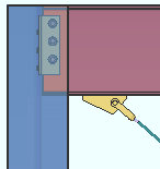
| Example 2: Same as example 1, except that " UFM special case design " is set to ' Special case 3 '. Also of relevance to this situation is the setup option " Design for a beam-column gusset if flange end distance is less than " in Plate Design Settings . |
|
***Various Framing Situations***
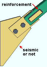
| Seismic and Non-Seismic HSS/TS Vertical Brace Reinforcement | |
| Connection Design Locks = " Brace Reinforcement " | |
|
Section size: HSS/TS |
| Framing situations: beam only, column only, beam & column, shared gusset to beam, shared gusset to column, column base/cap | |
|
Settings: " Pipe/tube end-fitting " = ' Welded ' or ' Paddle plate ' or ' Paddle plate (double shear) ' |
|
| Seismic or not: HSS vertical brace reinforcement plates are created automatically when " Seismic brace " is set to ' Yes '. To reinforce non-seismic HSS/TS braces, lock a non-zero " Plate thickness " in the " |
|
***Various Framing Situations***
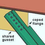
| Wide Flange Vertical Brace Bolted Directly to Gusset
Connection Design Locks = see the table below. |
|
| Section size: wide flange |
|
| Framing situations: See the table shown below. | |
|
Settings: " Web orientation " needs to be ' Vertical ' (under " |
|
| Comment: Other vertical brace wide flange connections discussed in this Connection Guide apply when " Side of gusset " is set to ' Center '. | |
| Connection Design Locks
( web-vertical wide flange vertical brace web field bolted to gusset ) |
|
| to a beam | Brace Connection To Gusset |
| to a column | Brace Connection To Gusset |
| to a beam & column | Brace Connection To Gusset |
| shared gusset, to a beam | Brace Connection To Gusset |
| shared gusset, to a column | Brace Connection To Gusset |
| to a column and base/cap plate | Brace Connection To Gusset |
***Various Framing Situations***
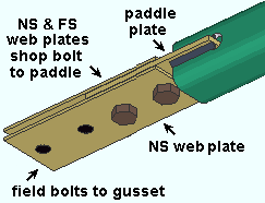
| HSS Vertical Brace with a Paddle (Double Shear) End Fitting | |
| Section size: HSS , pipe or tube
|
|
| Framing situations: See the table below. | |
|
Input connection type: ' Vbrc plate ' or ' User defined ' |
|
| Settings: " Pipe/tube end-fitting " must be set to ' Paddle (double shear) ' | |
| Connection Design Locks ( HSS, pipe or tube vertical brace ) |
|
| to a beam | Brace Conn To Guss Hss Paddle w/ Web Plates |
| to a column | Brace ConnTo Guss Hss Paddle w/ Web Plates |
| to a beam & column | Brace Conn To Gus Hss Paddle w/ Web Plates |
| shared gusset, beam | documentation in progress |
| shared gusset, column | documentation in progress |
| column base/cap | Brace Conn To Guss Hss Paddle w/ Web Plates |
***Vertical Brace to Beam Connections***
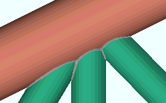
| Welded HSS Vertical Bracing (rectangular or round) | |
|
Section size: HSS round sections for all three braces. |
| Input connection type: ' Welded '. | |
| Comments: This works for a single brace, 2-point bracing, or for 3-point bracing (shown). | |
|
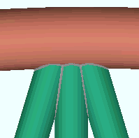
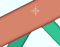
Another example of welded HSS round bracing. In this example, the top chord is a curved beam. During Process and Create Solids of 3-point bracing, connection design Exact Fits the center brace to the chord member, then Exact Fits the two outer braces to the center brace. |
|
An example of HSS rectangular bracing to an HSS rectangular beam. Note that the work point for the vertical brace does not go to the workline of the beam in this example. Also note that both braces are Exact Fit to the chord, but not to one another. |
| Welded Back-to-Back Double Angle Vertical Bracing | |
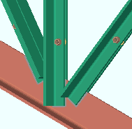
| Section size: Angle sections for all three braces. |
|
| Input connection type: ' Welded '. | |
| Comments: The beam must be a W tee or S tee. The braces weld to the stem of the tee. " Weld all around angle branch " and " Connection weld size " are setup options. | |
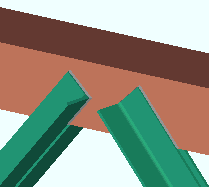
| Leg-up welded double-angle bracing to a W tee. Connections can be designed for a single or double leg-up angle brace in many framing conditions. Click here and here and here for other examples of leg-up connections. |
|
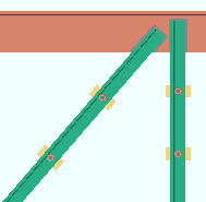
| Another example of back-to-back double-angle vertical bracing. Both of these braces go to the same point on the beam workline. If that point was below the work line, the connection would still be designed, but the left brace would be lower. " Brace to supporting member " and " Brace to brace " field clearances apply to this connection. |
|
| Vertical Brace to an HSS Round Beam | |
| Connection Design Locks = " Gusset One Member "
" Brace Connection To Gusset " " Weld Conn2 " |
|
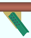
|
This example shows an angle brace to a HSS round beam. Even though HSS round is an " Invalid section size " for a beam, connection design can connect vertical braces to a HSS round beam. Use INCM to locate the brace on the beam's workline, or you may not get a connection. |
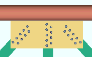
|
Here's an example of 3-point bracing to a HSS round beam. You might want to add a HSS round beam to use as a chord for a truss. |
| Single Angle Vertical Brace to a Beam | |
| Connection Design Locks = " Gusset One Member "
" Brace Connection To Gusset " " Weld Conn2 " |
|
| Section size: an angle section. |
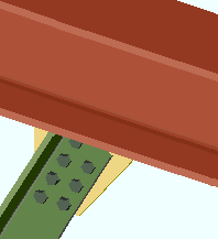
|
| Settings: ' Stagger bolts '. | |
| Comments: For single angle braces where the leg to gusset is 5 inches (127 mm) or longer, you have the option to set a staggered bolt pattern. | |
| An example of a leg-up angle vertical brace to a beam. Connection design can design a connection for a single or double " Angle leg turned up " brace in many framing conditions. Click here and here and here for other examples of leg-up connections. |
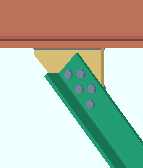
|
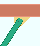
| HSS Vertical Brace (round or rectangular) Field Welded to a Gusset | |
| Connection Design Locks = " Gusset One Member " " Weld Conn2 " " Brace Connection To Gusset Hss Welded " | |
|
Section size: An HSS rectangular section (shown) or HSS round. |
| Settings: Field ' Welded ' to gusset, " Notch length clearance ," number of " Erection bolts " is ' One '. " Hole type for HSS erection bolts " is ' Standard round '. | |
| Comments: Connection design notches the brace to fit around the gusset for field welding. The bolt is a temporary erection bolt. | |
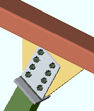
| HSS Vertical Brace (round or rectangular) Bolted to a Gusset | |
| Connection Design Locks = " Gusset One Member " " Weld Conn2 " " Brace Connection To Gusset HSS Bolted " | |
| Section size: A HSS rectangular section (shown) or a HSS round section. |
|
| Settings: Field ' Bolted ' to the gusset. | |
| Comments: The built-up tee end fitting shop welds to the HSS brace and field bolts to the gusset plate. | |
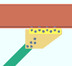
| Vertical Brace Gusset to a Beam with a Clip Angle | |
| Connection Design Locks = " Gusset One Member "
" Brace Connection To Gusset " " NS/FS Clip Conn2 " |
|
|
Section size: An angle section (shown) or a HSS round or HSS rectangular or channel or W tee or wide flange section. |
| Settings: ' Clip angle ' on gusset to beam. | |
| Comments: The alternative is to weld the gusset to the beam. | |
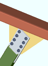
| HSS Vertical Brace (round or rectangular) with Paddle Plate | |
| Connection Design Locks = " Gusset One Member " " Weld Conn2 " " Brace Connection To Gusset HSS Paddle " | |
| Section size: An HSS rectangular section (shown) or a HSS round section. |
|
| Settings: ' Paddle plate ' as the end fitting. | |
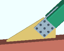
| Comments: The brace is notched and shop welds to the paddle plate. In this example, the paddle plate field bolts to the gusset, which shop welds to the supporting member (a beam). | |
| Here's an example with three columns of bolts. The larger the section size, the more columns of bolts connection design will design in the paddle plate. |
|
| Vertical Brace to a Web Horizontal Wide Flange Beam | |
| Connection Design Locks = " Gusset One Member "
" Brace Connection To Gusset " |
|
|
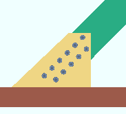
Section size: An angle section (shown) or a HSS round or HSS rectangular or channel or tee. |
| Comments: Connection design can create a vertical brace gusset to the web of a wide flange beam oriented web horizontal. | |
| Web Vertical Wide Flange Brace with Web Channel to a Rolled Beam | |
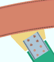
| Section size: A wide flange section between W6 and W30. |
|
| Settings: ' Vertical ' web orientation, ' Standard ' connection. " Web connection type " is set to ' Channel '. " Flange connection type " is set to ' None '. | |
| Stem-Vertical Tee Brace to Beam | |
| Connection Design Locks = " Gusset One Member " " Weld Conn2 " " Brace Connection To Gusset Wtee " | |
|
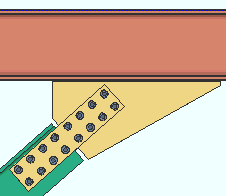
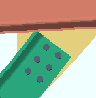
Settings: A W tee " Section size " with stem ' Vertical ' oriented ' Down ' (shown) or ' Up ' (not shown). The W tee brace's " Connection type " is ' Web plates '. ' VBrc plate ' is the " Input connection type ." |
| Comments: Connection design can create web plates on both sides of the brace web. Fill plates are designed if the stem (web) is thinner than the gusset. | |
|
Here's a similar situation to that shown above. The vertical brace is a stem-vertical W tee. However, the brace's " Connection type " is ' Coped flange '. You can't see the cut in this example, but the far side of the W tee's flange is coped so that its web can bolt directly to the gusset plate. Connection design locks are " Brace Conn To Gusset ." |
| Angle Vertical Brace with Clipped Gusset | |
| Connection Design Locks = " Gusset One Member "
" Brace Connection To Gusset " " Weld Conn2 " |
|
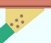
| Settings: An angle section (a single angle). The box must be checked for " |
|
| Comments: This applies to a single-angle vertical brace at a limited range of angles to a beam or to a beam and column. | |
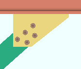
| Example of a single-angle vertical brace without a clipped gusset. This is how connection design designs the gusset plate when " |
|
***Vertical Brace to Column Connections***
| Angle Vertical Brace Pointed Leg Up | |
| Connection Design Locks = " Gusset One Member "
" Brace Connection To Gusset " " Weld Conn2 " |
|
|
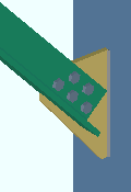
Section Size and Settings: An angle section. " Angle leg turned up " (checked). |
| Comments: Connection design can create a ' Vbrc plate ' for on a leg-up angle brace to a beam, column or shared gusset. It can design a ' Welded ' connection on a leg-up double-angle vertical brace (' Back to back ') to the stem of a W tee (or S tee) chord member. | |
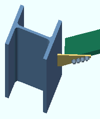
| Vertical Brace Skewed to a Column | |
| Connection Design Locks = " Gusset One Member "
" Brace Connection To Gusset " " Weld Conn2 " |
|
| Section size: Connections can be designed for a vertical brace of any of the normally permitted material types. An angle brace is shown. |
|
| Comments: Connection design creates a bevel groove weld with the appropriate " Groove angle ." You can get connections for skewed vertical braces to columns only, not to beams. | |
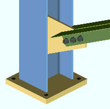
| Double-Angle Vertical Brace to Column | |
| Connection Design Locks = " Gusset One Member "
" Brace Connection To Gusset " " Weld Conn2 " |
|
|
Section size: An angle section. |
| Settings: ' Double material ', ' Back to back ', " Stitch plate gap ." | |
| Comments: Connection design creates a gusset plate that welds to the column web and bolts between the two angles. Connection design can also create connections on single angles or double angles in a "star" configuration. | |
|
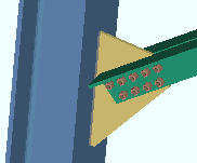
An example of a double-angle vertical brace to a sloping column. Connection design automatically rotates the brace so that its gusset aligns with the workline of the column. |
|
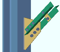
Another example of a double-angle vertical brace. The angles that make up this vertical brace are in a ' Star ' configuration. Stitch plates bolt the angles together. |
| Single Vertical Brace Welded to a Stiffened Column Web | |
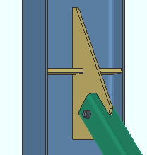
|
Comments: If a single vertical brace gusset plate is welded to the web of a supporting column, connection design is permitted to create a stiffener to reinforce the suporting member's web when " Check supporting member for web stress " is set to ' If required '. |
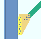
| Vertical Brace Gusset to Column with Clip Angle | |
| Connection Design Locks = " Gusset One Member "
" Brace Connection To Gusset " " Clip Angle2 " |
|
| Section size: A L section (shown) or a HSS round or HSS rectangular or C or W tee or W section. |
|
|
Settings: ' Clip angle ' ' Bolted ' to gusset. |
|
| Comments: The alternative is to weld the gusset to the column. | |
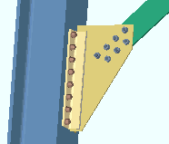
| Vertical brace gusset to a sloping column with welded clip angle. The ' Clip angle ' is ' Welded ' to the gusset and bolts to the column. The framing edge of the gusset aligns with the column. Use INCM to connect the vertical brace to the column. |
|
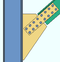
| Stem-Vertical Tee Brace to a Column | |
| Connection Design Locks = " Gusset One Member " " Weld Conn2 " " Brace Connection To Gusset Wtee " | |
|
Settings: A W tee " Section size " with stem ' Vertical ' oriented ' Down ' (shown) or ' Up ' (not shown). The W tee brace's " Connection type " is ' Web plates '. ' VBrc plate ' is the " Input connection type ." |
| Comments: Connection design creates web plates on both sides of the brace web. Fill plates are designed if the stem (web) is thinner than the gusset. | |
|
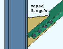
Here's a similar situation to that shown above. The vertical brace is a stem-vertical W tee, but in this example the " Connection type " is ' Coped flange ', thus resulting in the far side of the W tee's flange beign coped so that its web can bolt directly to the gusset plate. Connection design locks are " |
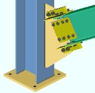
| Web Vertical Wide Flange Brace to a Column | |
| Connection Design Locks = " Gusset One Member ,"
" Brace Conn To Gusset Wide Flange Web Plate ," " Brace Conn To Gusset Wide Flange Flange Angle " |
|
| Section size: A wide flange section between W6 and W30. |
|
| Settings: ' Vertical ' web orientation, ' Standard ' connection. | |
| Comments: The gusset plate shop welds to the column. Connection design creates web connection plates and clip angles for field bolting the wide flange vertical brace to the gusset plate. | |
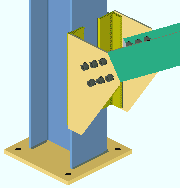
| Web Horizontal Wide Flange Brace to a Column | |
| Connection Design Locks = " Gusset One Member "
" Brace Connection To Gusset " " Weld Conn2 " |
|
|
Section size: A wide flange section between W6 and W30. |
| Settings: ' Horizontal ', ' Flange gussets '. | |
| Comments: The two gussets shop weld to the column or connect with welded clip angles (as is shown). The flanges of the wide flange vertical brace field bolt to the gussets. | |
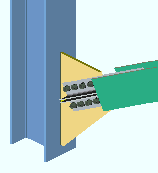
| Web Horizontal Wide Flange Brace to a Column | |
| Connection Design Locks = " Gusset One Member "
" Brace Connection To Gusset " " Weld Conn2 " |
|
| Section size: A wide flange section between W6 and W30. |
|
| Settings: ' Horizontal ', ' Claw angles '. Connection design looks first to the " Preferred Angle Sizes " list when choosing an angle size. | |
| Comments: The wide flange brace field bolts to the gusset with claw angles. | |
***Vertical Brace to Column and Base or Cap Plate***
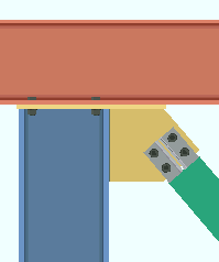
| Vertical Brace to Column & Auto Cap Plate | |
| Section size: A web horizontal wide flange (shown) or HSS rectangular or HSS round or angle or channel or W tee. |
|
| Framing condition: Vertical brace to beam-column. ' Auto base/cap plate ' must be selected to have the plate extended. | |
| Comments: The gusset shop welds to the cap plate and column. | |
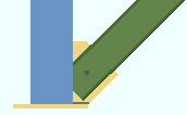
| Vertical Brace to Column & Base Plate | |
| Connection Design Locks = " Gusset Column Cap " " Weld Conn2 " | |
|
Section size: HSS rectangular section (shown) or HSS round or angle or channel or ' W tee ' or wide flange . |
| Comments: The gusset plate shop welds to both the column and base plate. | |
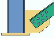
|
Another example of a vertical brace to column & base plate. This example shows an angle brace rather than a HSS rectangular brace. The base plate is a ' User Base Plate ' defined in the Base/Cap Plate Schedule . |
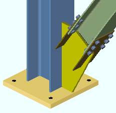
| Web Vertical Wide Flange Brace with Paddle Plates | |
| Connection Design Locks = " Gusset Column Cap ,"
" Brace Conn To Gusset Wide Flange Paddle " |
|
|
Section size: Wide flange between W6 and W30, or welded plate wide flange . |
| Settings: ' Vertical ' web orientation, ' Paddle plate ' connectors. " Vertical brace paddle plate gap " (setup). | |
| Comments: The notched paddle plates shop weld to the gusset and field bolt to the flanges of the vertical brace. | |
***Vertical Brace to Beam & Column Connections***
| Vertical Brace to a Beam & Column | |
| Connection Design Locks = " Gusset Beam Column "
" Brace Connection To Gusset " " NS/FS Clip Conn1 " |
|
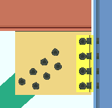
|
Section size: An angle section (shown) or a HSS round or HSS rectangular or channel or tee or' wide flange. |
| Comments: For this framing situation, connection design shop welds the gusset to the beam and field bolts to the column with a clip angle (shown) or end plate or shear plate (depending on the beam connection). | |
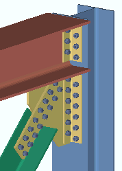
|
Another example of a vertical brace to a beam & column. This illustration shows a W tee " Section size " with stem ' Vertical '. Since the stem is ' Up ', the bottom bolt line aligns with the work line of the brace. If the stem were ' Down ', the top bolt line would align with the workline. |
| Vertical Brace to Beam & Column with Clip Angle | |
| Connection Design Locks = " Gusset Beam Column "
" Brace Connection To Gusset " " NS/FS Clip Conn1 " " NS/FS Clip Conn2 " |
|
| Settings: ' Clip angle ' on gusset to beam. |
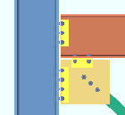
|
| Comments: The gusset can be field bolted with a clip angle to the beam on a vertical brace to beam & column when a clip angle shop bolts the gusset plate to the column. | |
| Here's another example of a vertical brace to beam & column. A ' Clip angle ' field bolts the gusset to the beam. The wide flange brace has ' Vertical ' web orientation and ' Paddle plate ' connectors. For more information on this connection, see Web Vertical Wide Flange Brace with Paddle Plates (on this page). |
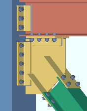
|
| A Beam's End Plate Combined to a Vertical Brace Gusset | |
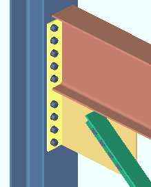
| Connection Design Locks = " Gusset Beam Column " " Brace Connection To Gusset " " End Plate " | |
|
Input connection type: ' End plate ' on the beam, ' Vbrc plate ' on the vertical brace. |
| Beam connection: ' Non-moment ', " Combine beam/vbr end plates " (set to ' Yes '). The end plate can be ' Wide gage ' or ' Narrow gage '. | |
| Framing condition: Vertical brace frames to a beam and column. The gusset welds to the beam and end plate. | |
|
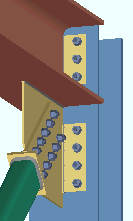
An HSS rectangular vertical brace with an end plate to the gusset that is NOT combined with the beam's end plate. The beam's end plate is set to ' No ' for " Combine beam/vbr end plates ." |
| A Beam's Shear Plate Combined to a Vertical Brace Gusset | |
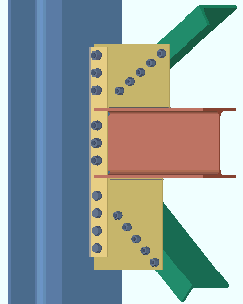
| Connection Design Locks = " Gusset Beam Column " " Brace Connection To Gusset " " Shear Tab " " Weld Conn2 " | |
| Input connection type: ' Shear plate ' on the beam, ' Vbrc plate ' on the vertical brace. |
|
| Beam connection: ' Non-moment ', " Combine beam/vbr shear plates " (set to ' Yes '). | |
| Framing conditions: Each of the two vertical braces in this example frames to the beam and the column. The example shows angle braces, but a connection like this one can also be generated for braces of other material types. | |
| An HSS round vertical brace with a shear plate to gusset that is NOT combined with the beam's shear plate. The beam's shear plate is set to ' No ' for " Combine beam/vbr shear plates ." |
|
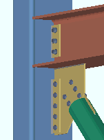
| Another example of a shear plate combined to a vertical brace. This example shows wide flange vertical braces. The shear plate shop welds to the column and therefore is detailed with the column. Both gusset plates shop weld to the beam and are therefore detailed with the beam. |
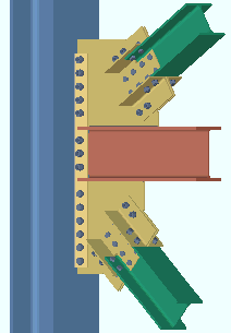
|
| In v2018 and newer, a vertical brace framed to a fully welded moment beam to column can get a designed connection. |
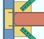
|
|
| Double-Angle Vertical Brace to a Beam & Column | |
| Connection Design Locks = " Gusset Beam Column " " Brace Connection To Gusset " " Weld Conn2 " " NS/FS Clip Conn1 " | |
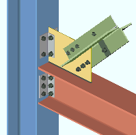
|
Section size: An angle section. |
| Settings: ' Double material ', ' Star ' | |
| Comments: For this framing situation, the gusset shop welds to the beam and field bolts to the column using a clip angle. Note that connection design includes "stitch plates" for bolting the two angles together into a star configuration. | |
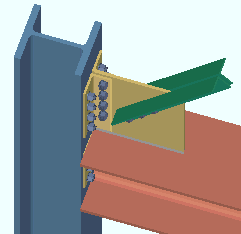
|
Another example of a double-angle vertical brace to beam & column. This illustration shows ' Double material ' ' Back-to-back ' with a " Stitch plate gap ." The gusset welds to the beam in this example, but can connect with a ' Clip angle '. |
|
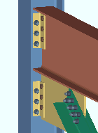
A leg-up double-angle vertical brace to a beam and column. Connection design can create a connection for a single or double " Angle leg turned up " brace in many framing conditions. Click here and here and here for other examples of leg-up connections. |
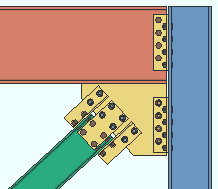
| Web Vertical Wide Flange, Standard Connection | |
| Connection Design Locks = " Gusset Beam Column " " Brace Connection To Gusset Wide Flange Web Plate " " Brace Connection To Gusset Wide Flange Flange Angle " " NS/FS Clip Conn1 " " Weld Conn2 " | |
| Section size: A wide flange section between W6 and W30. |
|
| Settings: ' Vertical ' web orientation, ' Standard ' connection. " Web connection type " is set to ' Web plates '. " Flange connection type " is set to ' Claw angles '. | |
| Beam-to-column connection: Clip angle. The gusset-to-column connection is also a clip angle. | |
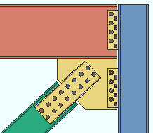
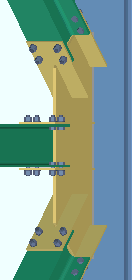
| Web vertical wide flange channel web connection: A variant on the ' Standard ' connection for wide flange vertical braces. The " Web connection type " is set to ' Channel '. The " Flange connection type " is set to ' None . |
|
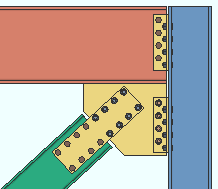
| Web vertical wide flange with a web plate connection: Another variation on the ' Standard ' connection for wide flange vertical braces. The " Web connection type " is set to ' Web plates ' and the " Flange connection type " is set to ' None '. |
|
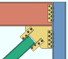
| Web vertical wide flange, claw angles: The " Web connection type " is set to ' None ' and the " Flange connection type " is set to ' Claw angles '. |
|
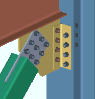
| Paddle Plate with More than Two Columns of Bolts | |
| Connection Design Locks = " Gusset Beam Column " " Weld Conn2 " " Brace Connection To Gusset " " NS/FS Clip Conn1 " | |
|
Section size: Paddle plates on larger HSS sections (round or rectangular) are designed with more than two columns of bolts. |
| Comments: Paddle plates may be designed for any framing condition. Connection design uses a minimum column spacing of 3 x bolt diameter to determine how many columns can fit on the paddle plate. | |
***Vertical Brace Intersection Connections***
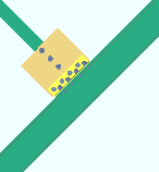
| Vertical Brace Connecting to a Wide Flange Vertical Brace | |
| Connection Design Locks = " Gusset One Member "
" Brace Connection To Gusset " " NS/FS Clip Conn2 " |
|
|
Section size: An angle section (shown) or a HSS round or HSS rectangular or C or W tee or W section. |
| Settings: ' Clip angle ' on gusset to brace. | |
| Comments: You also have the option to weld the gusset to the W brace. | |
|
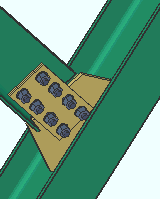
Another example of a vertical brace connecting to a wide flange vertical brace. This example is a stem-vertical W tee vertical brace framing to a wide flange vertical brace. You can get the same types of vertical brace connections to a wide flange vertical brace as you can to a beam. |
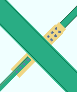
| Intersecting Vertical Braces of Different Material Types | |
|
Restrictions: The supporting vertical brace must be a wide flange with web vertical (shown) or web horizontal (not shown). |
| Variations: The supported braces can be angle (shown), HSS rectangular (shown), HSS round, channel, W tee or wide flange. You can ' Weld ' (shown) or ' Clip angle ' the gusset to the W vertical brace. | |
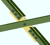
| Vertical Brace Intersection Plate | |
| Connection Design Locks = " Gusset Intersection "
" Brace Connection To Gusset " |
|
| Section size: An angle section (double angle shown) or a HSS round or HSS rectangular or channel or W tee or wide flange. |
|
| Comments: Connection design can create an intersection plate for framing situations similar to that shown. The two shorter braces share a work point where the longer brace bolts to the plate. | |
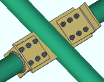
| An intersection plate for HSS round vertical braces. Connection design automatically notches the supporting brace and welds that brace to the intersection plate. |
|
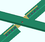
| An intersection plate for angle braces with their legs turned up. Connection design can create a connection for a single or double " Angle leg turned up " brace in many framing conditions. Click here and here and here for other examples of leg-up connections. |
|
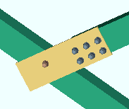
| Single-Side Vertical Brace Intersection Plate | |
| Connection Design Locks = " Gusset Intersection " " Brace Connection To Gusset " | |
|
Section size: An angle section. |
| Input connection type: ' Vbrc plate '. | |
| Comments: You can also get a single side vertical brace intersection plate using angle " Double material " in a ' Back to back ' configuration. | |
|
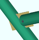
A single-sided intersection plate for HSS round vertical braces. Connection design automatically notches the supporting brace and welds that brace to the intersection plate. HSS rectangular braces work the same way. |
|
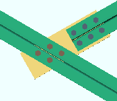
A single-sided intersection plate for W tee vertical braces. |
***Vertical Brace Shared K Connections***
|
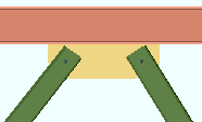
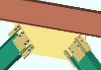
| Vertical Braces with a Shared Gusset | |
| Connection Design Locks = " Gusset 2 Point " " Weld Conn2 " " Brace Connection To Gusset HSS Welded " | |
|
Section size: ' HSS rectangular ' (shown) or ' HSS round ' or ' angle ' or ' channel ' or ' tee ' or ' wide flange '. |
| Comments: The braces must be closer together than a setup value . | |
|
Another example of 2-point vertical bracing. This example shows wide flange vertical braces with webs vertical. |
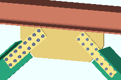
|
Another example of 2-point vertical bracing. This example shows stem-vertical tee braces with web connection plates. |
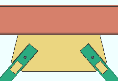
|
Seismic 2--point gusset plates can be designed. when " Seismic brace " is set to ' Yes '. In this example, " |
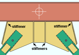
|
Stiffeners can be added to 1st edition 2-point seismic gusset plates. You get 1st edition design when " |
|
|
| Three Vertical Braces with Shared Gusset | |
| Connection Design Locks = " Gusset 3 Point " " Brace Connection To Gusset " " Weld Conn2 " | |
| Section size: angle (double shown) or wide flange or HSS rectangular or a HSS round or channel or tee. |
|
| Framing condition: For W or HSS rectangular or stem vertical WT, all three braces must be the same material. A 3-point gusset must be ' Welded ' to the support. | |
| Another example of 3-point vertical bracing. The section sizes and framing situations that apply to 3-point vertical bracing is described above . In this example, the three braces are wide flange braces with paddle plates, which are discussed above . Notice that this example shows three vertical braces framing to a column. The example above shows vertical braces framing to a beam. In both examples, the center brace is perpendicular to the supporting member. |
 |
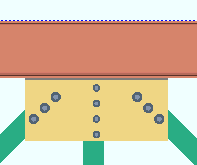
| Different Bolt Diameters on Braces to a Shared Gusset | |
| In this example, the " NM bolt diameter " for the center brace is smaller than the bolts used on the two outside braces. Angle braces are shown, but this can also be done for other brace material types. |
|
