"  Outer Flange Plate " & "
  Butt Plate " & "
  Upper Outer Flange Fill Plate " & "
  Lower Outer Flange Fill Plate "
| Column flange splice plates are designed per " |
|
|||||
"  |
" (" 
|
||||
|
" (values of ' 0 ' if fill plate not designed) 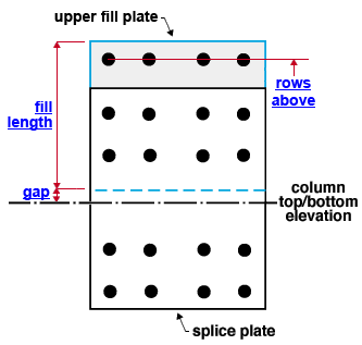 |
" (values of ' 0 ' if fill plate not designed) 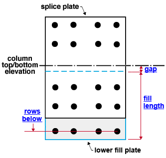 |
||||
|
|||||
Connection Guide: Click here , here and here for related screen shots. For welded splice plates , only the " Butt plate thickness " applies.
User Defined Connections: Settings that are locked (
) in a user defined connection file will automatically be locked on a member edit window for which that file is the " Input connection type ." You can, if you so choose, manually lock additional settings on the member edit window, and your changes will be retained, through multiple processes, so long as you do not change to a different connection then switch back to the original user defined connection.
Column Edit: To change a setting, first set it to locked (
). Related settings that are unlocked (
) may be updated, and the "
Left/Right end limit state " calculations will be updated. Settings that are locked (
) will not be changed by connection design , even if doing so might prevent a connection failure.
Connection design locks :
| Locks not dimensioned or called out on the drawing are marked ( not depicted ). |
![]() Outer Flange Plate
Outer Flange Plate
(column splice connection)
Outer flange plate
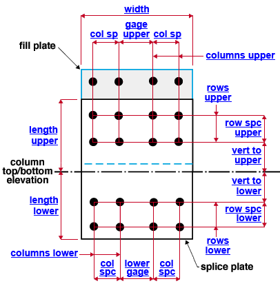
Plate length lower ( length lower ): The distance (parallel with the work lines of the columns) from the top work point (" End elevation ") of the lower column to the bottom edge of the splice plate (see example ). If the splice plate connection is designed with a butt plate, the top work point of the lower column is the exact center of the top surface of the butt plate. If " Plate length lower " is unlocked (
), changing the bolt " Rows " (lower) or " Vertical spacing " (lower) also changes the " Plate length lower ." " Vertical to holes " (lower) moves the holes without affecting the plate length.
Plate length upper ( length upper ): The distance (parallel with the work lines of the columns) between the bottom " End elevation " of the upper column and the top edge of the splice plate (see example ). If " Plate length upper " is unlocked (
), changing the bolt " Rows " (upper) or " Vertical spacing " (upper) also changes the " Plate length upper ." As the " Plate length upper " changes, the " Upper fill length " also changes. " Vertical to holes " (upper) moves the holes without affecting the plate length.
Plate width ( width ): The length of the top or bottom edge of the flange splice plate (see example ). If the column is perfectly vertical, " Plate width " is the horizontal distance between the two vertical edges of the splice plate. If " Plate width " is unlocked (
), changing the bolt " Columns " or " Horizontal gage " (upper) or " Horizontal spacing " (upper) or " Horizontal gage " (lower) or " Horizontal spacing " (lower) may also change the " Plate width ."
End connection failure message: Bolt edge distance on flange plate not within read min/max values
Plate thickness ( not depicted ): The " Material thickness " of the flange splice plate. This applies to the splices for both flanges.
Field bolts on the upper column
Bolt diameter ( not depicted ): You can either type in any diameter (inches or mm), or you can select a bolt diameter from the combo box (
). The diameters that are listed in the combo box come from Home > Project Settings > Job > Bolt Settings > the " Available bolt diameters " list. The bolt diameter entered here (together with the " Hole type ") sets the diameter of holes through the part of the plate that bolts to the flange of upper column. It applies to splices for both flanges.
Hole type ( not depicted ): Standard round or Short slot or Oversized or Long slot or User slot #1 or User slot #2 . The hole type selected here, together with the " Bolt diameter " entered above, set the diameter of holes through the part of the plate that bolts to the flange of upper column.
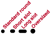
Rows ( rows upper ): The number of rows of bolts on the part of the flange splice plate that is above the bottom " End elevation " of the upper column. Bolt row spacing runs parallel with the work lines of the columns being spliced -- see example . If " Plate length upper " is unlocked (
), changing the number of bolt " Rows " (upper) also changes the " Plate length upper . "
Vertical to holes ( vert to upper ): The distance (parallel with the work lines of the columns) from the bottom work point (" End elevation ") of the upper column to the center of the nearest row of bolts that is above that " End elevation " (see example ). Changing the " Vertical to holes " moves the holes on the upper half of the flange plate without affecting the plate dimensions.
Vertical spacing ( row spc upper ): The distance (center to center) between any two adjacent rows of bolts on the part of the splice plate that field bolts to the flange of the upper column. Bolt row spacing runs parallel with the work lines of the columns being spliced -- see example . If " Plate length upper " is unlocked (
) and the number of bolt " Rows " (upper) is ' 2 ' or greater, changing the bolt row " Vertical spacing " (upper) also changes the " Plate length upper ."
Columns ( columns upper ): Half the total number of columns of bolts on the part of the flange splice plate that is above the bottom " End elevation " of the upper column. Bolt column spacing runs perpendicular to the work lines of the columns being spliced -- see example . For the splice plate connection represented in the example above, the number of " Columns " is ' 2 ', which results in a total of four bolt columns on the upper section of the flange plate. If " Plate width " is unlocked (
), changing the number of " Columns " may also change the " Plate width ."
End connection failure message: Bolt column on flange splice should be 1 only
Horizontal spacing ( col sp ): The distance (center to center) between any two adjacent columns of bolts other than the two inside bolt columns (see example ). If " Plate width " is unlocked (
) and the number of bolt " Columns " is ' 2 ' or greater, changing the bolt row " Horizontal spacing " (upper) may also change the " Plate width ."
Horizontal gage ( gage upper ): The distance (center to center) between the two inside columns of bolts on the part of the splice plate that field bolts to the flange of the upper column (see example ). If " Plate width " is unlocked (
), changing the " Horizontal gage " (upper) may also change the " Plate width ."
Shop bolts on the lower column
Bolt diameter ( not depicted ): You can either type in any diameter (inches or mm), or you can select a bolt diameter from the combo box (
). The diameters that are listed in the combo box come from Home > Project Settings > Job > Bolt Settings > the " Available bolt diameters " list. The bolt diameter entered here (together with the " Hole type ") sets the diameter of holes through the part of the plate that bolts to the flange of lower column. It applies to the splices for both flanges.
Hole type ( not depicted ): Standard round or Short slot or Oversized or Long slot or User slot #1 or User slot #2 . The hole type selected here, together with the " Bolt diameter " entered above, set the diameter of holes through the part of the plate that bolts to the flange of lower column.

Rows ( rows lower ): The number of rows of bolts on the part of the flange splice plate that is below the top " End elevation " of the lower column. Bolt row spacing runs parallel with the work lines of the columns being spliced. For the splice plate connection represented in the example above, the number of bolt " Rows " (lower) is ' 2 '. Entering ' 0 ' for bolt " Rows " (lower) is allowed for a welded lower/bolted upper splice connection. Users will still need to add the weld since this isn't a supported connection. If " Plate length lower " is unlocked (
), changing the number of bolt " Rows " (lower) also changes the " Plate length lower ."
Vertical to holes ( vert to lower ): The distance (parallel with the work lines of the columns) from the top work point (" End elevation) " of the lower column to the center of the nearest row of bolts that is below that " End elevation " (see example ). If the splice plate connection is designed with a butt plate, the top work point of the lower column is the exact center of the top surface of the butt plate. Changing the " Vertical to holes " (lower) moves the holes on the lower half of the flange plate without affecting the plate dimensions.
Vertical spacing ( row spc lower ): The distance (center to center) between any two adjacent rows of bolts on the half of the splice plate that shop bolts to the flange of the lower column. Bolt row spacing runs parallel with the work lines of the columns being spliced -- see example . If " Plate length lower " is unlocked (
) and the number of bolt " Rows " (lower) is ' 2 ' or greater, changing the bolt row " Vertical spacing " (lower) also changes the " Plate length lower ."
Columns ( columns lower ): Half the total number of columns of bolts on the part of the flange splice plate that shop bolts to the flange of the lower column. Bolt column spacing runs perpendicular to the work lines of the columns being spliced -- see example . For the splice plate connection represented in the example above, the number of bolt " Columns " (lower) is ' 2 ', which results in a total of four bolt columns on the lower section of the flange plate. If " Plate width " is unlocked (
), changing the number of bolt " Columns " may also change the " Plate width ."
Horizontal spacing ( col spc ): The distance (center to center) between any two adjacent columns of bolts other than the two inside bolt columns (see example ). Bolt column spacing runs perpendicular to the work lines of the columns being spliced, parallel with the depths of those members. If " Plate width " is unlocked (
) and the number of bolt " Columns " (lower) is ' 2 ' or greater, changing the bolt column " Horizontal spacing " may also change the " Plate width ."
Horizontal gage ( lower gage ): The distance (center to center) between the two inside columns of bolts on the part of the splice plate that shop bolts to the flange of the lower column (see example ). If " Plate width " is unlocked (
), changing the " Horizontal gage " (lower) may also change the " Plate width ."
End connection failure message: Bolt edge distance on flange plate not within read min/max values
![]() Upper Outer Flange Fill Plate
Upper Outer Flange Fill Plate
(for splicing a less deep top column to a bottom column)
Upper outer flange fill plate
Upper fill length ( fill length ): The distance (parallel with the work lines of the columns) from the fill plate edge at the upper fill gap to the top edge of the fill plate (see example ). Changing the " Upper fill length " moves the top edge of the fill plate while the bottom edge of the plate remains fixed at the " Upper fill gap " distance from the top column's bottom " End elevation ." If " Upper fill length " is unlocked (
), changing the number of " Rows above plate " also changes the " Upper fill length ." The " Upper fill length " also changes as the flange plate's " Plate length upper " changes.
Upper fill thickness ( not depicted ): The " Material thickness " of the upper fill plate.
Upper fill gap ( gap ): The distance (parallel with the work lines of the columns) from the bottom work point (" End elevation ") of the upper column (the center of the top face of the butt plate, if there is one) to the bottom edge of the fill plate (see example ). The bottom edge of the upper fill plate is fixed at the " Upper fill gap " distance from the bottom work point " End elevation " of the upper column.
Rows above plate ( rows above ): The number of rows of holes on the upper fill plate that are above the splice plate. Row spacing runs vertically, parallel with the work lines of the two columns being spliced. For the splice plate connection represented in the example above, the number of " Rows above plate " is ' 1 '. If " Upper fill length " is unlocked (
), changing the number of " Rows above plate " also changes the " Upper fill length ." Setting the " Rows above plate " at ' 0 ' aligns the top edge of the upper fill plate with the top edge of the flange plate.
![]() Lower Outer Flange Fill Plate
Lower Outer Flange Fill Plate
(provides field clearance when the two columns being spliced have equal depths)
Lower outer flange fill plate
Lower fill length ( fill length ): The distance (parallel with the work lines of the columns) from the fill plate edge at the lower fill gap to the bottom edge of the fill plate (see example ). Changing the " Lower fill length " moves the bottom edge of the fill plate while the top edge of the plate remains fixed at the " Lower fill gap " distance from the bottom column's top " End elevation ." If " Lower fill length " is unlocked (
), changing the number of " Rows below plate " also changes the " Lower fill length ." The " Lower fill length " also changes as the flange plate's " Plate length lower " changes.
Lower fill thickness ( not depicted ): The " Material thickness " of the lower fill plate.
Lower fill gap ( gap ): The distance (parallel with the work lines of the columns) from the top work point (" End elevation ") of the lower column to the bottom edge of the fill plate (see example ). The top edge of the lower fill plate is fixed at the " Lower fill gap " distance from the top work point " End elevation " of the lower column.
Rows below plate ( rows below ): The number of rows of holes on the lower fill plate that are below the splice plate. Row spacing runs vertically, parallel with work lines of the two columns being spliced. If " Plate length lower " is unlocked (
), setting the number of " Rows below plate " at ' 0 ' results in a " Lower fill length " that aligns the bottom edge of the fill plate with the bottom edge of the flange plate. Increasing the number of " Rows below plate " increases the " Lower fill length " based on the distance entered for " Vertical spacing " (lower).
![]() Butt Plate
Butt Plate
(for both welded and bolted column splices)
Butt plate
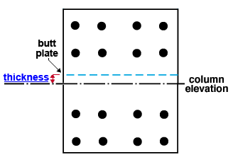
Butt plate thickness ( thickness ): The " Material thickness " of the butt plate. A butt plate is designed when the box for "
Butt plate " is checked. When the " Column attachment " is ' All-Bolted plates ', a butt plate may also be designed (even with "
Butt plate " not checked) if the upper column's nominal depth is at least 2 inches less than the lower column's nominal depth. The example at the top of the page shows a bolted splice connection. A butt plate may also be designed when the " Column attachment " is ' Welded '.


