Column Splice ("  Connection specifications " and more)
Also see :
- Column Splice for W Columns with Same Section Sizes (connection guide)
- Web Plates on Columns with Bolted Flange Splices (connection guide)
- Column Splice for W Columns with Different Section Sizes (connection guide)
- Field Welded Column Splices for Tube Columns (connection guide)
- Field Welded Splice with Bolted Channel Web Connection (connection guide)
- Field Welded Splice with Welded Channel Web Connection (connection guide)
- Column (index)
- Setup for column splice connections (index)
Design restrictions for column splices :
------"  Connection specifications " for column ' Splice plate ' connections ------
| A column's " |
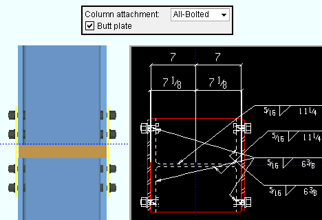
Column attachment: All-Bolted plates or Welded or Bolted/Welded plates .
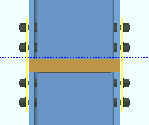
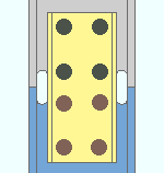
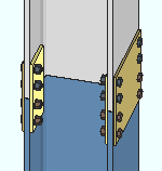
' All-Bolted plates ' instructs connection design to create flange splice plates that shop bolt to the lower column. The columns being spliced can be a flanged shape such as wide flange, S shape or welded plate W. A " Butt plate " can optionally be shop welded to the top of the column shaft being spliced.
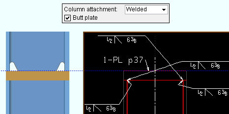
' Welded ' specifies that the two columns be field welded. The columns can be wide flange, S shape, welded plate W, welded plate box, pipe or tube. A " Butt plate " can optionally be added. For shapes that have flanges, an "
End preparations "' > " Top/bottom flange operation " > ' Cope field weld ' operation is automatically applied, and a " Channel web connection " can optionally be added . Field welds are generated in the 3D model for flanged shapes, but do not appear on the shop drawings ( member details ). The field welds may optionally be detailed on erection view drawings (" Show 3D field welds "). Shop welds are generated for shop attachment of a butt plate as designated on the bottom column's detail and may optionally be shown on erection view drawings (" Show 3D shop welds ").
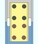
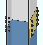
' Bolted/Welded plates ' instructs connection design to create flange splice plates that shop weld to the lower column and field bolt to the top column. The columns being spliced can be wide flange, S shape or welded plate W. A " Butt plate " can optionally be shop welded to the top of the column shaft being spliced.
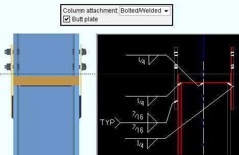
Advanced Selection: ColumnAttachmentIsBolted
Parametric module: ColumnAttachmentIsBolted
Connection design locks (' Bolted '): "Outer Flange Plate " "
Butt Plate " "
Upper/Lower Outer Flange Fill Plate "
Non-bearing splice: ![]() or
or ![]() . This applies only when the Design Settings > " Connection Design Method " is ' EUROCODE 3 ' or ' EUROCODE 3 UK '.
. This applies only when the Design Settings > " Connection Design Method " is ' EUROCODE 3 ' or ' EUROCODE 3 UK '.
If this box is checked (
), connection design considers the column splice connection to be non-bearing, as described in Joints in Steel Construction: Simple Joints to Eurocode 3 , section 6 (2011). Such splices allow for a gap between the upper and lower columns.
If the box is not checked (
), no gap is designed between the columns.
|
|
If this box is checked (
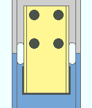
), connection design creates a butt plate that shop welds to the top of the column being spliced.
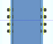
If the box is not checked (
), a butt plate is not designed and, if ' Welded ' is selected for splicing columns with flanges, a " Channel web connection " can optionally be designed. Exception: For flanged columns of unequal depths with bolted splice plates, connection design creates a butt plate even when this box is not checked.
Setup: " Butt plate material grade "
Connection design locks: "Butt Plate "
|
|
If this box is checked (
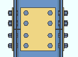
), connection design creates web connection plates for columns that are spliced together with ' All-Bolted ' flange splice plates. The plates are designed on both the near and far sides of the column web. Tip : Increasing the " Horizontal shear " on both columns increases the plate thickness and number of rows of bolts in the web plates. Click here for an example in the Connection Guide.
If the box is not checked (
), no web plates are designed. Exception: You may get web plates if a " Horizontal shear " load has been entered.
Advanced Selection: WebPlates
Parametric module: WebPlates
Connection design locks: "Web Plate "
Channel web connection: ![]() or
or ![]() . This "
. This " ![]() Connection specifications " option applies to flanged columns that are field ' Welded '. Flanged columns are, for example, wide flange, S shape and welded plate W columns.
Connection specifications " option applies to flanged columns that are field ' Welded '. Flanged columns are, for example, wide flange, S shape and welded plate W columns.
|
|
If this box is checked (
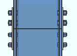
), connection design splices together the webs of the two columns with NS and/or FS channel sections. The channel section size is selected based on column nominal depth and weight per Home > Project Settings > Fabricator > Standard Fabricator Connections > Column splice setup > the " Channel splice section size selection " table. The channel(s) shop bolt to the bottom column (when " Channel lower connection " is ' Bolted ') and field bolt to the top column.
If the box is not checked (
), the two columns continue to be field ' Welded ', but without a channel web connection.
Advanced Selection: ChannelWebConnection
Parametric module: ChannelWebConnection
Connection design locks: "Web Channel "
Channel lower connection: Bolted or Welded . This " ![]() Connection specifications " option applies to flanged columns when the option "
Connection specifications " option applies to flanged columns when the option " ![]() Channel web connection " is turned on (checked).
Channel web connection " is turned on (checked).
|
|
' Bolted ' instructs connection design to shop bolt the channel web connection to the lower column and field bolt to the upper column. The connection is auto detailed with the lower column.
' Welded ' specifies that the lower part of the channel web splice be shop welded to and detailed on the lower column. The upper part of the channel web connection is field bolted.
Advanced Selection: ChannelLowerConnection
Parametric module: ChannelLowerConnection
Connection design locks: "Web Channel "
Channel connection side: Near side or Far side or Both . This " ![]() Connection specifications " option sets the side(s) of the column web on which the channel is to be attached. The near side of a column with zero rotation is the web that faces the bottom of your computer screen in a plan view. For column shafts over 30 feet long or over 100 lbs per foot, channels are designed on both sides of the web regardless of the choice made here.
Connection specifications " option sets the side(s) of the column web on which the channel is to be attached. The near side of a column with zero rotation is the web that faces the bottom of your computer screen in a plan view. For column shafts over 30 feet long or over 100 lbs per foot, channels are designed on both sides of the web regardless of the choice made here.
|
|
|
|
' Near side ' fastens the channel connection to the near side web of the column.
' Far side ' fastens the channel connection to the far side web of the column.
' Both ' instructs connection design to create a channel connection on both sides of the column web.
Advanced Selection: ChannelConnectionSide
Parametric module: ChannelConnectionSide
Connection design locks: "Web Channel "
Splice plate grade: Auto or user-entered .
'
Auto ( checked )' specifies that connection design apply a setup choice ( Home > Project Settings > Fabricator > Standard Fabricator Connections > Plates > the " Splice Plates " section > " Plate material grade ").
'
Auto ( not checked )' lets you select a steel grade in the list box (
). Choices in the list box come from Home > Project Settings > Job > Plate Grades .
Gap between upper and lower column: A distance between the upper and the lower columns being spliced. This applies to a " Non-bearing splice " only when the Design Settings > " Connection Design Method " is ' EUROCODE 3 ' or ' EUROCODE 3 UK '.
Inner flange plate: Automatic or Yes or No . This applies to column splice connections with ' All-Bolted plates '. Each column " Section size " must be a flanged shape such as wide flange. Fill plates may be designed if the upper and lower columns are different section sizes.
|
|
' Automatic ' instructs connection design to apply the choice made at Home > Project Settings > Fabricator > Standard Fabricator Connections > Column Splice Settings > " Use inner flange plates ."
' Yes ' specifies that connection design attempt to design inner flange plates and, where necessary, fill plates for column splice connections. The length of such inner flange plates is always equal to that of the outer flange plates.
' No ' turns off the design of inner flange plates for column splice connections.
Connection design locks: "
Inner flange plates "
