The Edit Image window ( Drawing Editor )
Images are PNG, GIF, JPEG or TIFF graphic files. They can be placed in any type of drawing. They can be printed, or they can serve as temporary templates for tracing or orientation. To more accurately visualize how an image will look when printed, set your " Drawing Editor background color " to white.
Format (.ext) Applications Descriptions GIF (.gif) logos, line drawings, icons GIF and PNG are similar, compressed formats. PNG is newer. Both allow transparency. PNG (.png) JPEG (.jpg, .jpeg) photographs The JPEG format can be used for photorealistic images. TIFF (.tif, .tiff) logos, line drawings A TIFF image converted into a GIF or PNG takes up less space.
- To open this window:
- Image Edit or double-click an image
- Image Edit All
- Select image, right-click, choose " Edit " on the context menu
Also see :
- Images (topic)
- Add Image (tool)
- To move an image (drag its center in Select Items mode)
- To re-size an image (drag its edge in Select Items mode)
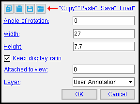
 " Copy " " Paste " " Save " " Load " buttons :
- You'll find buttons like these at the top of this window. They apply to all user-editable settings that are on this window. Click here for more information.
- " Save " (
 ) saves a "form" file to the
  form/sheet-image folder that is used by your current version of this program. Give the form a name that will help users in other Jobs on your network identify its purpose. " Load " (
  ) changes all settings on this window to those settings that are stored in the file that you select.
- " Paste " and " Load " replace mixed entries to a single field with a single entry. " Copy " and " Save " ignore fields with mixed entries, treating them as if they have no entry or do not exist.
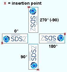
Angle of rotation: Any positive or negative (-) number of degrees.
|
' 0 ' (zero) leaves the image unrotated -- in the same orientation it had in the drawing it was created from. A ' positive number ' rotates the symbol counterclockwise that number of degrees around its insertion point. A ' negative (-) number ' rotates the symbol clockwise that number of degrees. |
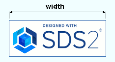
Width: The length (in the primary dimension " Units " or other units ) of a horizontal edge of the image when its " Angle of rotation " is ' 0 ' (zero). If " Keep display ratio " is checked, changing the " Width " also proportionally adjusts the " Height " so that the same width/height ratio is maintained.
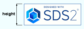
Height: The length (in the primary dimension " Units " or other units ) of a vertical edge of the image when its " Angle of rotation " is ' 0 ' (zero). If " Keep display ratio " is checked, changing the " Height " also proportionally adjusts the " Width " so that the same width/height ratio is maintained.
Keep display ratio
Keep display ratio
If this box is checked (
If the box is not checked (
Warning : Once you change the display ratio by re-sizing an image in one direction, the old display ratio is forgotten. You can't recheck this box to get it back.


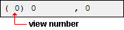
Attached to view: A number designating the view that this image is attached to. This applies mainly to member details . For instance, a column detail may have a view of face A, face B and face C. It may also have various section views (Section A-A, Section B-B, Section C-C). All graphical objects that are in a particular view are assigned the same number. The only other type of drawing on which you might find multiple views is a submaterial detail .
Assigning the correct number to an object (line, weld symbol, label, etc.), prevents Shorten and Unshorten problems on submaterial details and member details . Automatically detailed submaterial details and member details are the two Drawing Editor drawing types that can have multiple views.
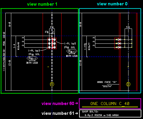
To show a view's number, you can add the X-Y-Z Display to your toolbar. An alternative decoration you can add to display view numbers is the X-Y Dual Show/True Display .
In the Drawing Editor , the X-Y-Z Display shows the view number that the point location target (
) is over.
Troubleshooting: If you Unshorten a drawing then Shorten , only to find that objects are repositioned in a way that seems wrong, the problem might be that the objects are attached to a view that is not the view that they should be attached to. A good troubleshooting method is to select all of the objects that you believe should be attached to the same view, then right-click ( Menu ) and choose " Edit " on the menu . This will open the Multi-Items Edit window. Look at the " Attached to view " field on that window. If that field is gray (shows no view number), then that field has a mixed entry , indicating that objects in your selection have have two or more different view numbers. Entering the desired view number to the " Attached to view " multi-edit field assigns all objects in your selection that one view number.
View number assignment is fairly random. While view numbers assigned during auto detailing are generally the same as the numbers assigned to views in member isolation (or material isolation's edit views mode ), there are cases where that general one-to-one correspondence will not hold. Also, while the main view of a member detail is almost always view 0, the other views are assigned numbers as they are added, and since the order in which views are added is arbitrary, there is little correspondence between a view's number and its type.
How can objects be assigned wrong view numbers? When a user adds an object to a drawing on which there are multiple views (a member detail or a submaterial detail), it is the responsibility of that user to ensure that the object is attached to the correct view. That sounds like an easy thing to do, but it isn't always so simple. Take, for example, a pointer . When a user adds a pointer using Objects > Pointers > Add , the user does not see the Pointer Edit window and therefore does not see the " Attached to view " entry field. Pointers can also be added using Paste , Paste at Original Location , Paste Repeatedly , Paste Special , Paste to Several , Add Standard Detail , Add Standard Detail to Several , Add Weld Combo , Hole Sym Combo , Label Combo , etc. Each of these tools is a different way for users to add a pointer to a wrong view.
Layer: The layer of your current drawing that this image is on.
On a sheet or sheet outline: Unless you have added a layer using Layer Add or the Layer Panel, there will be only one layer (' Layer 0 '). Consequently, all graphics will be on that one layer.
On a member detail or erection view: The default selected layer is the " User annotation " layer. The selected layer is the layer that subsequently added graphics -- including images -- are added to.
To close this window
![]()
![]()
"OK" (or the Enter key) closes this window and applies your changes to the image that you just edited.
Note: You must Save changes made to the affected image using this window in order to make your changes permanent. You can Undo before or after you Save.
"Cancel" (or the Esc key or the ![]() button) closes this window without changing the image.
button) closes this window without changing the image.

