 Intersection Real/Member (INRM) ( Modeling & Drawing Editor )
Tool summary :
Also see :
- Modeling and the Drawing Editor (where INRM can be found)
- REFD (in Modeling , may be used with INRM to locate points on a reference drawing)
- Reference drawing ( Modeling -- may be various drawing types)
- Annotation text ( Display Options in Modeling )
- Member worklines (found by INRM )
- Lines (found by INRM )
- Circles (found by INRM )
- Arcs (found by INRM )
 Examples ( Modeling ) :
|
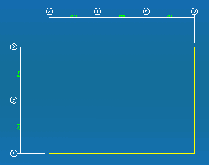
This reference drawing uses yellow lines to draw a grid. In Modeling . INRM together with REFD could be used to locate intersections of lines, arcs or circles with member worklines . |
|
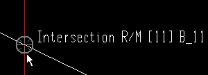
An INRM point being snapped to in the model. Annotation text identifies the member being snapped to. Reference drawing lines are covered by beams. |
A drawing like that shown above, where lines are used to designate a grid, might have been generated using Drawing Conversion to import an AutoCAD engineering design drawing into the Drawing Editor . The converted drawing could then be brought into Modeling as a reference drawing, where it could be used to aid member layout and checking. In actuality, the drawing shown above was created as a job standard detail in the Drawing Editor .
page 1 | contents | locate > | top
 Locating a point using INRM ( Modeling ) :
1 . Begin this operation in Modeling .
1a : Open ( Ctrl + o ) a view that shows the members in the model that you want to find INRM points on.
1b (if needed) : In Reference Drawing Tools , set the reference drawing you want to find INRM points on to "
Show ." Reference drawings that you want turned off should be set to "
Show ."
1c : Invoke any tool that requires the use of a Locate option to designate points. For example, invoke Add Member or Add Grid Line if you want to add members or new views. If all you want to do is check the coordinates of intersections, you might want to use Construction Line Add .
2 . Various Locate options become active, and the status line prompts you to locate a point.
|
|
|
The REFD locator |
2a : Turn on the REFD locator (if it's not on already). To do this, you can select the REFD icon or choose Locate > Intersection of real line and member or select REFD on the Set Location Mode toolbar item.
2b : Turn on the INRM locator. To do this, you can select the INRM icon or choose Locate > Intersection Real Line/Member or select INRM on the Set Location Mode toolbar item.
2c : Place the mouse pointer (
) so that the point location target (
) snaps to the nearest intersection of a real line with a member line. The X-Y-Z display tells you the global coordinates of the snapped-to point.
2d : Continue to perform the operation you began in step 1c, or move your mouse pointer to a different INRM point and verify that point's location.
page 1 | contents | locate > | top
 Examples ( Drawing Editor ) :

|
An INRM point being snapped to on a erection view in the Drawing Editor . Annotation text identifies the member being snapped to. |

|
In this example, the member is drawn with a " Steel member style " of ' Wire '. Notice that INRM still snaps to the member line . |
page 1 | contents | locate > | top
 Locating a point using INRM ( Drawing Editor ) :
INRM is a Locate option that can be used on a erection view drawing in the Drawing Editor to locate a point where a member work line intersects another member workline or a line or a circle or an arc . A member's work line can be found regardless of the " Steel member style " that the member is drawn in. As shown in the examples above, during point location, an INRM point is marked with the text " Intersection R/M ."
1 . Begin this operation in a erection view drawing in the Drawing Editor . It does not matter what " Steel member style " the members shown on that drawing are drawn in.
1a : Invoke Add Line or Construction Line Add or any other tool that permits the use of INRM as a Locate option.
2 . Various Locate options become active, and the status line prompts you to locate a point.
2a : Select the INRM icon or choose Locate > Intersection Real Line/Member or , if you want to use Auto point location, move your mouse pointer near a construction line and member intersection as described in step 2b.
2b : Place the mouse pointer (
) so that the point location target (
) snaps to the point of intersection with a work line that is nearest to the mouse pointer. The X-Y-Z display shows the coordinates of the point. Left-click ( Locate ) to locate (place) a point at the center of the target.
2c : Continue to perform the operation you began in step 1a.
Tip: For second point location (step 3 if these instructions were to continue), you can optionally type in a distance and/or angle to constrain the second point to the typed-in distance/angle from the first point. The distance/angle you type will be shown in brackets [ ] in the status line .


