Position and Match Marks (per-drawing setup overrides)
Also see :
- Home > Project Settings > Fabricator > Position and Match Marks (setup window that this window can override)
page 1 | contents | settings > drawing settings | top
To open setup overrides for Position and Match Marks :
Method 1 : In the Drawing Editor , with a '
Detail ' (auto detailed) as your current drawing, choose Settings > Drawing Settings > Position and Match Marks.
page 1 | contents | settings > drawing settings | top
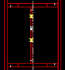
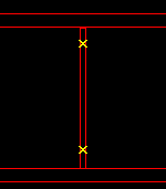
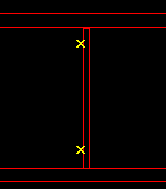
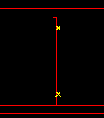
![]() Perpendicular shear tabs:
Perpendicular shear tabs: ![]() Auto or
Auto or ![]() Center of plate or
Center of plate or ![]() Left face or
Left face or ![]() Right face or
Right face or ![]() Framing face of plate . The choice made here applies to your current drawing (if that drawing is a member detail), and if you Detail Current Piecemark with templates. It also applies if, after exiting the drawing, you select that drawing for Detail Members with templates . Furthermore, the member detail needs to depict a non-moment single-plate shear connection. This also applies to a shear plate that connects a vertical brace gusset plate to a column.
Framing face of plate . The choice made here applies to your current drawing (if that drawing is a member detail), and if you Detail Current Piecemark with templates. It also applies if, after exiting the drawing, you select that drawing for Detail Members with templates . Furthermore, the member detail needs to depict a non-moment single-plate shear connection. This also applies to a shear plate that connects a vertical brace gusset plate to a column.
|
'
Auto ' instructs automatic detailing with templates to apply the setup choice made to " perpendicular shear tabs ."
'
Center of plate ' results in dimensioning to the center of the plate the next time auto detailing with templates is done for your current drawing.
'
Left face ' instructs auto detailing with templates to dimension to the surface of the shear plate that faces left on the supporting member's detail.
'
Right face ' is the surface of the shear plate that faces right on the supporting member's detail.
'
Framing face of plate ' is the face of a plate that attaches to the supported beam.
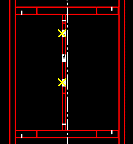
![]() Beam web single stiffener plates:
Beam web single stiffener plates: ![]() Auto or
Auto or ![]() Center of plate or
Center of plate or ![]() Left face or
Left face or ![]() Right face . The choice made here applies to dimensioning on your current beam detail if that drawing depicts a single stiffener plate and if you Detail Current Piecemark with templates. It also applies if, after exiting the drawing, you select that drawing for Detail Members with templates .
Right face . The choice made here applies to dimensioning on your current beam detail if that drawing depicts a single stiffener plate and if you Detail Current Piecemark with templates. It also applies if, after exiting the drawing, you select that drawing for Detail Members with templates .
|
'Auto ' instructs automatic detailing with templates to apply the setup choice made to " Beam web single stiffener plates ."
'
Center of plate ' results in dimensioning to the center of the plate the next time auto detailing with templates is done for your current beam detail.
'
Left face ' is the surface of the stiffener plate that faces left on the beam's detail.
'
Right face ' is the surface of the stiffener plate that faces right on the beam's detail
Modeling: You can get single beam stiffener plates in the model when an auto base/cap plate or user base/cap plate has been set to " Use transverse beam stiffener " and the " Load " on the column is sufficiently low that only a single stiffener is generated in the beam that is under or above that column. That beam's detail will be the drawing that depicts a single beam stiffener plate.
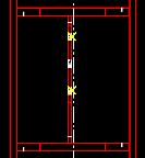
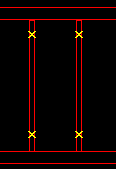
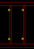
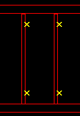
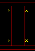
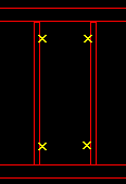
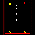
![]() Beam web double stiffener plates:
Beam web double stiffener plates: ![]() Auto or
Auto or ![]() Center of plate or
Center of plate or ![]() Left face or
Left face or ![]() Right face or
Right face or ![]() Outside faces of plate or
Outside faces of plate or ![]() Inside faces of plate . The choice made here applies to dimensioning on your current beam detail if that drawing depicts a double stiffener plates and when you select that column detail for Detail Current Piecemark with templates. It also applies if, after exiting the drawing, you select that drawing for Detail Members with templates .
Inside faces of plate . The choice made here applies to dimensioning on your current beam detail if that drawing depicts a double stiffener plates and when you select that column detail for Detail Current Piecemark with templates. It also applies if, after exiting the drawing, you select that drawing for Detail Members with templates .
|
|
Auto ' instructs automatic detailing with templates to apply the setup choice made to " Beam web double stiffener plates ."
'
Center of plate ' results in dimensioning to the center of the plate the next time auto detailing with templates is done for your current beam detail.
'
Left face ' is the surface of the stiffener plate that faces left on the beam's detail.
'
Right face ' is the surface of the stiffener plate that faces right on the beam's detail
'
Outside faces of plate ' are the two vertical surfaces (one on each plate) that face away from each other.
'
Inside faces of plate ' are the two vertical surfaces (one on each plate) that face toward each other.
Modeling: You can get double beam stiffener plates in the model when an auto base/cap plate or user base/cap plate has been set to " Use transverse beam stiffener " and the " Load " on the column is sufficiently high that two stiffeners are generated in the beam that is under or above that column. That beam's detail will be the drawing that depicts a double stiffener plates.
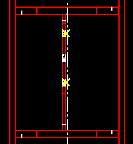
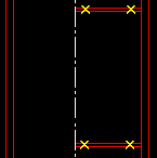
![]() Column to beam flange plates:
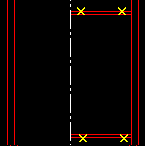
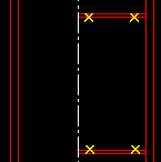
Column to beam flange plates: ![]() Auto or Center of plate or Top face or Bottom face or Outside faces of plate or Inside faces of plate . The choice made here applies to dimensioning on your current column detail if that drawing depicts bolted moment flange plates to a column web or stability plates for to-column-web shear plate connections. It applies when you select that column detail for Detail Current Piecemark with templates. It also applies if, after exiting the drawing, you select that drawing for Detail Members with templates .
Auto or Center of plate or Top face or Bottom face or Outside faces of plate or Inside faces of plate . The choice made here applies to dimensioning on your current column detail if that drawing depicts bolted moment flange plates to a column web or stability plates for to-column-web shear plate connections. It applies when you select that column detail for Detail Current Piecemark with templates. It also applies if, after exiting the drawing, you select that drawing for Detail Members with templates .
|
|
Auto ' instructs automatic detailing with templates to apply the setup choice made to " Column to beam flange plates ."
'
Center of plate ' results in dimensioning to the center of the plate the next time auto detailing with templates is done for your current column detail.
'
Top face ' is the surface of the plate that faces the top of the column detail.
'
Bottom face ' is the surface of the plate that faces the bottom of the column detail.
'
Outside faces of plate ' are the two horizontal surfaces (one on each plate) that face away from each other.
'
Inside faces of plate ' are the two horizontal surfaces (one on each plate) that face toward each other.
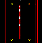
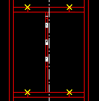
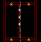
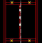
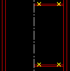
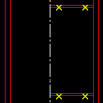
![]() Column flange stiffener plates: Center of plate or Top face or Bottom face or Outside faces of plates or Inside faces of plates . The choice made here applies to dimensioning on your current column detail if that drawing depicts column flange stiffeners opposite to a beam moment connection. It applies when you select that column detail for Detail Current Piecemark with templates. It also applies if, after exiting the drawing, you select that drawing for Detail Members with templates .
Column flange stiffener plates: Center of plate or Top face or Bottom face or Outside faces of plates or Inside faces of plates . The choice made here applies to dimensioning on your current column detail if that drawing depicts column flange stiffeners opposite to a beam moment connection. It applies when you select that column detail for Detail Current Piecemark with templates. It also applies if, after exiting the drawing, you select that drawing for Detail Members with templates .
The ' Top face ' refers to the top of the plate as it appears on the member detail. The options ' Inside/outside faces of plates ' apply to two plates that are parallel to one another; the surfaces of those plates which face each other are the inside faces; the faces which look away from one another are outside faces.
|
|
Auto ' instructs automatic detailing with templates to apply the setup choice made to " Column flange stiffener plates ."
'
Center of plate ' results in dimensioning to the center of the plate the next time auto detailing with templates is done for your current column detail.
'
Top face ' is the surface of the plate that faces the top of the column detail.
'
Bottom face ' is the surface of the plate that faces the bottom of the column detail.
'
Outside faces of plate ' are the two horizontal surfaces (one on each plate) that face away from each other.
'
Inside faces of plate ' are the two horizontal surfaces (one on each plate) that face toward each other.
Modeling: Column flange stiffeners opposite to a moment connection may be designed when "
Design for stiffeners " is checked for a bolted or welded moment connection to a column flange.
page 1 | contents | settings > drawing settings | top
To close Position and Match Marks :
"OK" (or the Enter key) closes the Position and Match Marks window and saves the overrides on it with your current drawing, presumably so that the next time that drawing undergoes member detailing those override settings are applied to the detail.
To permanently save your override changes, you need to save your current drawing. If you close your current drawing without saving changes made to it, any changes to override settings that you have applied to that drawing will be forgotten. On the other hand, a Drawing Overrides List will show active overrides (non-auto settings) that have been applied to your current drawing even if that drawing has not yet been saved.
"Cancel" (or the Esc key or the ![]() button) closes this window without saving any changes made to it.
button) closes this window without saving any changes made to it.
"Reset" undoes all changes made to this window since you first opened it. The window remains open.
page 1 | contents | settings > drawing settings | top

