"  Moment " Options (on Beam Edit & User Defined Connections windows)
For connection design to create a moment connection :
- The beam's " Section size " must be a flanged shape such as wide flange.
- Seismic moment connections can be designed per " Seismic " settings.
" Moment " options :
Also see :
- Setup for moment connections (index)
- Connection guide (examples of moment connections)
Moment type: Non-moment or Bolted or Welded . This " ![]() Moment " option is available on the Beam Edit window and at Home > Project Settings > Job > User Defined Connections . For connection design to create a moment connection, the " Section size " set for this beam in "
Moment " option is available on the Beam Edit window and at Home > Project Settings > Job > User Defined Connections . For connection design to create a moment connection, the " Section size " set for this beam in " ![]() General settings " must be a flanged shape such as wide flange , welded plate wide flange or S shape .
General settings " must be a flanged shape such as wide flange , welded plate wide flange or S shape .
|
|
|
|||
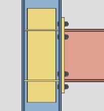
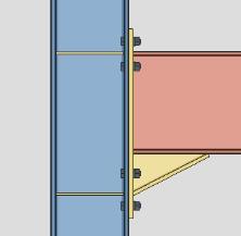
wide flange beam to the flange of a wide flange column |
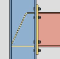
wide flange beam to a HSS column |
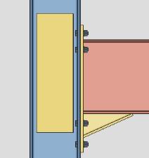
wide flange beam to the web of a wide flange column |
wide flange beam to the flange of a wide flange column |
' Non-moment ' specifies that the connection for this end of the beam be a non-moment connection. A " Moment load " is not auto calculated and cannot be user-entered. Options in the "
' Bolted ' instructs connection design to create a bolted moment connection. This option may be applied when ' Clip angle ' or ' Bent plate ' or ' End plate ' or ' Shear ' or ' Splice plate ' has been selected as the " Input connection type " for this beam. Connection design can create bolted moment connections with ' Plate ' as the moment connection " Connection material " on beams that slope as much as 30 degrees from horizontal.
' Welded ' applies when ' Shear ' or ' Clip angle ' or ' Bent plate ' or ' Fully welded moment ' is the " Input connection type " and the beam is a wide flange or a similar flanged shape and frames to a column. ' Shear ' is the only option for a beam framing to the web of a wide flange column. Connection design can create welded moment connections on beams that slope as much as 30 degrees from horizontal. A back-up bar may optionally be included as part of the connection, per the setup instructions entered at Home > Project Settings > Job > Moment Plate Design Settings > the " Back-up Bars on Welded Connections " tab > " Create solids for back-up bars in modeling ."
An unique situation: If the " Input connection type " is ' Fully welded moment ' the " Moment type " is automatically set to ' Welded '. Before you can change the " Moment type " to ' Bolted ' or ' Non-moment ', you first need to change the " Input connection type ."
Status Display: Member status > Left end moment type and Right end moment type
Status Display: Connection type > Fully welded moment .
Connection Guide: bolted moment to flange , welded moment to flange , welded moment to web , fully welded moment connection ()
Report Writer: Member.LeftEnd.MoreEnd.UserConnection.MomentTypeDescription
Advanced Selection: m.Ends[0].MomentType
Parametric module: m.Ends[0].MomentType
Design for doublers: ![]() or
or ![]() . This "
. This " ![]() Moment " option applies when ' Bolted ' or ' Welded ' has been selected as the " Moment type " and when this end of the beam frames to the flange of a column whose " Section size " is a flanged shape such as wide flange. The option is available on the Beam Edit window and at Home > Project Settings > Job > User Defined Connections .
Moment " option applies when ' Bolted ' or ' Welded ' has been selected as the " Moment type " and when this end of the beam frames to the flange of a column whose " Section size " is a flanged shape such as wide flange. The option is available on the Beam Edit window and at Home > Project Settings > Job > User Defined Connections .
|
|
|
|
If this box is checked (
), connection design initially creates the connection with web doubler plates only if doublers are necessary given the " Moment load " on this end of the beam. Connection design locks for "
If the box is not checked (
), connection design does not check to see if doublers are needed and, as a result, will not design doublers. A warning in the Connection Design Calculations and Expanded Connection Design Calculations tells you that the check has been turned off. Also, the following warning is displayed under "
Column web/flange design checks removed Setup: Home > Project Settings > Job > Moment Plate Design Settings > "To Column Flange" tab > " Web doublers " section
Connection design locks: "
Design for stiffeners: ![]() or
or ![]() . This "
. This " ![]() Moment " option applies when this beam end's " Moment type " is ' Bolted ' or ' Welded ' and that same end of the beam frames to the flange of a column whose " Section size " is a flanged shape such as wide flange. The option is available on the Beam Edit window and at Home > Project Settings > Job > User Defined Connections .
Moment " option applies when this beam end's " Moment type " is ' Bolted ' or ' Welded ' and that same end of the beam frames to the flange of a column whose " Section size " is a flanged shape such as wide flange. The option is available on the Beam Edit window and at Home > Project Settings > Job > User Defined Connections .
|
|
|
|
If this box is checked (
Column Flange Stiffeners " become available regardless of whether or not the stiffeners are actually designed. If valid entries are made to one or more of these locks, flange stiffeners are designed per those entries even if the stiffeners are not required.
If the box is not checked (
Column web/flange design checks removed Stiffener thicknesses: " Determine plate thickness by " is set at Home > Project Settings > Job > Moment Plate Design Settings . If the box is checked for " Use miscellaneous plates list ," connection design looks to Home > Project Settings > Fabricator > Standard Fabricator Connections > Plates > the " Column Stiffeners " tab for a suitable plate thickness.
Home > Project Settings > Job > Moment Plate Design Settings : " Corner operation " (' Cope ' or ' Clip '), " Corner operation sized by " (a method and a distance), " Design depth " (' As needed ' or ' When needed use full depth ' or etc.) and " Total stiffener clearance " (a distance).
Connection design locks: "
Column reinforcement type: Doublers and stiffeners or Morris stiffeners or Doublers only or Stiffeners only or Neither doublers nor stiffeners. This applies to fully welded moment connections and moment end plate connections when the Connection design method is EUROCODE 3 or EUROCODE 3 UK. The default setting can be changed at Home > Project Settings > Job > Design > Moment Plate Design Settings > Reinforcement Type.
Doublers and Stiffeners will reinforce the column with web doubler plates and stiffener plates if required by connection design. This will result in a moment end plate without a haunch.
Morris stiffeners will reinforce the column with Morris stiffener plates if required by connection design. This will result in a moment end plate without a haunch.
Doublers only will reinforce the column with web doubler plates if required by connection design. This will result in a moment end plate with a haunch.
Stiffeners only will reinforce the column with stiffeners if required by connection design. This will result in a moment end plate with a haunch.
Neither doublers nor stiffeners will not reinforce the column with additional materials. This will result in a moment end plate with a haunch.
Column web doubler side: Automatic or Both or NS or FS . This " ![]() Moment " option can be found on the Beam Edit window and at Home > Project Settings > Job > User Defined Connections .
Moment " option can be found on the Beam Edit window and at Home > Project Settings > Job > User Defined Connections .
' Both '

|
' NS ' (near side)
 |
' FS ' (far side)
 |
' Automatic ' applies a setup choice ( Home > Project Settings > Job > Moment Plate Design Settings > " Doubler plates on column web ").
' Both ' specifies that connection design create doubler plates on both sides of column webs when doubler plates are required. The thickness of each of these two doubler plates will likely be less than if only one doubler plate were used.
' NS ' instructs connection design to create a single doubler plate on the near side of the column web. This single doubler plate may be as thick as the combined thicknesses of doubler plates on both sides of the web.
' FS ' configures connection design to create a single doubler plate on the far side of the column web.
Connection material: Plate or Angle . This " ![]() Moment " option applies when ' Bolted ' is the " Moment type " and ' Clip angle ' or ' Bent plate ' or ' Shear ' is the " Input connection type " set in the beam's "
Moment " option applies when ' Bolted ' is the " Moment type " and ' Clip angle ' or ' Bent plate ' or ' Shear ' is the " Input connection type " set in the beam's " ![]() Connection type " leaf. Only ' Plate ' connection material can be designed for ' Splice ' connections. The option can be found on the Beam Edit window and at Home > Project Settings > Job > User Defined Connections .
Connection type " leaf. Only ' Plate ' connection material can be designed for ' Splice ' connections. The option can be found on the Beam Edit window and at Home > Project Settings > Job > User Defined Connections .
|
|
' Plate ' applies to most bolted moment flange connections. Connection design can create moment connections with flange plates on beams that slope as much as 30 degrees from horizontal.
' Angle ' can be selected for shear and clip angle and bent plate connections for beams framing to column flanges when the moment load is fairly low (since only a limited number of bolts can be fastened to an angle). Because the legs of an angle are at 90 degrees to one another, connection design can only create moment flange angles on non-sloping (horizontal) beams unless the beam frames to a sloping column. Also, there must be angle material entered to Home > Project Settings > Fabricator > Standard Fabricator Connections > " Preferred Angle Sizes ." If there is no angle material in this list (or if appropriate sizes are not listed), connection design will default to plate material for the connection.
Connection type: AISC or MBMA or Eurocode . This " ![]() Moment " option applies when this beam end's " Moment type " is ' Bolted ' and the same end's " Input connection type " is ' End plate '. The option can be found on the Beam Edit window and at Home > Project Settings > Job > User Defined Connections .
Moment " option applies when this beam end's " Moment type " is ' Bolted ' and the same end's " Input connection type " is ' End plate '. The option can be found on the Beam Edit window and at Home > Project Settings > Job > User Defined Connections .
' AISC ' stands for American Institute of Steel Construction. Related "
' MBMA ' stands for Metal Building Manufacturers Association. You may select this option to design flush or extended multi-row moment end plate connections on a wide flange or S shape or welded plate wide flange beam. Be aware, though, that only a limited range of section sizes are allowed. Related "
' Eurocode ' does not appear as an option when a " Connection design method " other than ' EUROCODE3 ' or ' EUROCODE UK ' is selected. When the " Connection design method " is ' EUROCODE UK ' or ' EUROCODE3 ', ' Eurocode ' is automatically selected as the " Connection type ."
Use inner flange plates: Automatic or Yes or No . This " ![]() Moment " option applies when the beam end's " Moment type " is ' Bolted ' and the same end's " Input connection type " is ' Shear '. The option can be found on the Beam Edit window and at Home > Project Settings > Job > User Defined Connections .
Moment " option applies when the beam end's " Moment type " is ' Bolted ' and the same end's " Input connection type " is ' Shear '. The option can be found on the Beam Edit window and at Home > Project Settings > Job > User Defined Connections .
|
|
|
' Automatic ' applies a setup choice ( Home > Project Settings > Job > Design Settings > " Use inner flange plates for beam splice moment ").
' Yes ' specifies that connection design design the bolted moment connection using inner flange plates. A total of four inner flange plates may be designed: 1) an upper NS inner flange plate, 2) an upper FS inner flange plate, 3) a lower NS inner flange plate and 4) a lower FS inner flange plate.
' No ' instructs connection design to create only top and bottom bolted moment flange plates.
Connection design locks: "
Connection Guide: Splice Plates with moment flange pates and inner flange plates .
End plates: Stiffened flush end or Unstiffened flush end or Stiffened extended end or Unstiffened extended end or Flush end or Extended end . This " ![]() Moment " option can be found on the Beam Edit window and at Home > Project Settings > Job > User Defined Connections .
Moment " option can be found on the Beam Edit window and at Home > Project Settings > Job > User Defined Connections .
When the " Connection type " is ' MBMA ':
' Stiffened flush end ' makes the edge of the end plate flush with the flange. Placement of the stiffener is the specified " Pattern " (' Pl below tension bolts ' and ' Pl between tension bolts ' are the two settings).
' Unstiffened flush end ' makes the edge of the end plate flush with the flange. No stiffener are designed. ' 2-bolt ' and ' 4-bolt ' are the two " Pattern " settings.
' Stiffened extended end ' extends the end plate beyond the flange and designs a triangular stiffener between the two bolts that are beyond the flange. ' 4-bolt ' and ' 1/3 unstiffened ' are " Pattern " settings that control the number of bolts inside the flange for this configuration.
' Unstiffened extended end ' extends the end plate beyond the flange, but without a stiffener. ' 4-bolt ' and ' 1/2 unstiffened ' and ' 1/3... '. are " Pattern " settings that control the number of bolts inside the flange for this configuration.
When the " Connection type " is ' Eurocode ':
' Flush end ' stops a row of bolts from being added above the top haunch or below the bottom haunch when haunches are designed with all "
). An extra row of inner bolts may still be added immediately above or immediately below the top/bottom flange when no haunches are designed. Positioning of bolts depends on the " Location " that is selected.
' Extend end ' adds a row of bolts above the top haunch when the " Location " is ' Top only '. It adds rows of bolts both above the top haunch and below the bottom haunch when the " Location " is ' Top & bottom '. It works in a similar fashion, placing extra bolts outside the flanges, when there is no haunch.
Tip: Connection design lock options for the positioning of bolt rows inside or outside of the beam's flanges are available in the "
Location: Top only or Top & bottom . This " ![]() Moment " option applies when ' End plate ' has been entered for this end of the beam as the " Input connection type " and the beam's " Section size " is a flanged shape such as wide flange. The " Moment type " must be ' Bolted '. The moment end plate " Connection type " can be ' AISC ' or ' MBMA ' or ' Eurocode '.
Moment " option applies when ' End plate ' has been entered for this end of the beam as the " Input connection type " and the beam's " Section size " is a flanged shape such as wide flange. The " Moment type " must be ' Bolted '. The moment end plate " Connection type " can be ' AISC ' or ' MBMA ' or ' Eurocode '.
|
| The AISC ' Top only ' end plate extends below the bottom flange. The MBMA ' Top only ' end plate is flush to the bottom flange. |
|
|
| The Eurocode " Location " options apply to extended-end end plates with or without haunches. They also apply to flush-end end plates. |
Framing situations: End plates may be applied to beam-to-column or beam splice framing situations. Sloping bolted moment end plate connections (
Bolt pattern: 8-bolt (' AISC ' only) or 4-bolt (' AISC ' or ' MBMA ') or 2-bolt (' MBMA ' only) or 1/2 unstiffened (' MBMA ' only) or Pl below tension bolts (' MBMA ' only) or Pl between tension bolts (' MBMA ' only) or 1/3 stiffened (' MBMA ' only) or 1/3 unstiffened (' MBMA ' only). This applies only to end plate moment connections. Together with " Location " (and " End plates " for ' MBMA '), this " ![]() Moment " option sets the design of the moment end plate.
Moment " option sets the design of the moment end plate.
' 8-bolt ' applies only when ' AISC ' is the moment end plate's " Connection type ." The moment connection is designed with a stiffener.
' 4-bolt ' applies when ' AISC ' or ' MBMA ' is the moment end plate's " Connection type ." For a moment plate extended above the top flange, two bolts are above the flange, and two bolts below the flange. For a moment plate that is flush with the flange, the four bolts are below the flange.
' 2-bolt ' applies to ' MBMA ' only. The end plate is designed to be flush with both flanges. Two bolts directly beneath the top flange and two other bolts directly above the bottom flange fasten the plate to the column.
' 1/2 unstiffened ' applies to ' MBMA ' only. For a moment plate extended above the top flange, one bolt is above the flange on the near side of the web, and two bolts are below the flange on the near side of the web. A corresponding number of bolts are on the far side of the web.
' Pl below tension bolts ' applies to ' MBMA ' only. The plate is flush with both flanges. For a ' Top only ' configuration, two rectangular stiffener plates (one NS, one FS) are designed below the four tension bolts under the top flange. This arrangement is mirrored for the bottom flange when ' Top and bottom ' is selected.
' Pl between tension bolts ' applies to ' MBMA ' only. The plate is flush with both flanges. For a ' Top only ' configuration, two rectangular stiffener plates (one NS, one FS) are designed between the four tension bolts under the top flange. This arrangement is mirrored for the bottom flange if ' Top and bottom ' is selected.
' 1/3 stiffened ' applies to ' MBMA ' only. For a moment plate extended above the top flange, one bolt is above the flange on the near side, and three bolts are below the flange on the near side. A corresponding number of bolts are on the far side of the plate. A rectangular stiffener is designed between the two bolts that are in the extension above the top flange.
' 1/3 unstiffened ' applies to ' MBMA ' only. For a moment plate extended above the top flange, one bolt is above the flange on the near side, and three bolts are below the flange on the near side. A corresponding number of bolts are on the far side of the plate. No stiffener plate is designed.
Bolt type: Auto or A325N or A325SC or A325X or etc. This " ![]() Moment " option applies to the moment components of a moment connection. For example, it sets the type of bolts in bolted moment flange plates, moment flange angles, moment splice plates (flange plates only) and moment end plates.
Moment " option applies to the moment components of a moment connection. For example, it sets the type of bolts in bolted moment flange plates, moment flange angles, moment splice plates (flange plates only) and moment end plates.
'
'
). Choices shown in that list box come from Home > Project Settings > Job > Bolt Specifications .
Bolt types for non-moment components of a moment connection are the " NM bolt type to supported " and/or " NM bolt type to supporting " that are specified under "
Bolt diameter: Auto or a user-entered diameter (inches or mm). This " ![]() Moment " option applies to the moment components of a moment connection. For example, it it sets the diameter of bolts for bolted moment flange plates or flange angles, moment splice plates (flange plates only) and moment end plates.
Moment " option applies to the moment components of a moment connection. For example, it it sets the diameter of bolts for bolted moment flange plates or flange angles, moment splice plates (flange plates only) and moment end plates.
| diameter |
|
'
'
The bolt diameter for non-moment components of a moment connection is the " NM bolt diameter " that is specified for this end of the beam. Non-moment components of a moment connection may be clip angles, bent plates, a shear plate or web splice plates.
Bolt incrementation: Connection design may increment the diameter of bolts up to 1 1/2 inch for an AISC moment end plate so that the connection stands up to the " Moment load ." For other moment designs (e.g., bolted flange plates or angles), connection design does not increment the bolt diameter. Connection design references the " Available bolt diameters " list when incrementing bolt sizes.
Connection design lock: "
Report Writer: Member.LeftEnd.MoreEnd.MinimumMomentBoltDiameter
Advanced Selection: MinimumMomentBoltDiameter
Parametric module: MinimumMomentBoltDiameter
Re-entrant cut: Automatic or Alternate 3 or Alternate 1 . This " ![]() Moment " option applies to non-seismic ' Welded ' moment connections. The option is disabled ( grayed out ) when " Seismic moment connection " is set to ' Yes ' (or ' Automatic ' and the setup choice is ' Yes ').
Moment " option applies to non-seismic ' Welded ' moment connections. The option is disabled ( grayed out ) when " Seismic moment connection " is set to ' Yes ' (or ' Automatic ' and the setup choice is ' Yes ').
|
||||||
| See the AISC Thirteenth Edition , pg. 16.1-328. |
' Automatic ' specifies that connection design apply a setup choice ( Home > Project Settings > Job > Weld Design Settings > " Re-entrant cut " > ' Alternate 1 ' or ' Alternate 3 ').
' Alternate 3 ' instructs connection design to use the " Re-entrant cut radius " that is entered in Weld Design Settings . The " Top flange operation " and " Bottom flange operation " under "
' Alternate 1 ' configures connection design to apply the values entered to the Weld Design Settings window for " Alternate 1 re-entrant cut radius " and " Alternate 1 re-entrant cut length " and " Alternate 1 re-entrant cut depth " and " Alternate 1 flange flush length ." The " Top flange operation " and " Bottom flange operation " under "
Groove angle: Automatic or 0 or 15 or 30 or 45 or 60 . This " ![]() Moment " option applies when a ' Welded ' moment connection has its " Re-entrant cut " set to ' Alternate 3 ' or ' Alternate 1 '. The option is disabled ( grayed out ) when " Seismic moment frame member " is set to ' Yes ' (or ' Automatic ' and the setup choice is ' Yes ').
Moment " option applies when a ' Welded ' moment connection has its " Re-entrant cut " set to ' Alternate 3 ' or ' Alternate 1 '. The option is disabled ( grayed out ) when " Seismic moment frame member " is set to ' Yes ' (or ' Automatic ' and the setup choice is ' Yes ').

|
|
|
|
|
' Automatic ' specifies that connection design apply a setup choice ( Home > Project Settings > Job > Weld Design Settings > " Groove angle ").
' 0 ' or ' 15 ' or ' 30 ' or ' 45 ' or ' 60 ' instructs connection design to cut the flange of the beam at the specified groove angle.
Also see: Weld preparation settings under Home > Project Settings > Job > Weld Design Settings > " Moment connections " apply under the same conditions that this " Groove angle " applies.
Haunch location: Auto or None or Top or Bottom or Both . This appears as a " ![]() Moment " option when the Home > Project Settings > Job > Design Settings > " Connection design method " is ' EUROCODE 3 ' or ' EUROCODE 3 UK '. To get a haunch, the beam end's " Input connection type " needs to be ' End plate ' or ' User defined ', and the " Moment type " needs to be ' Bolted '.
Moment " option when the Home > Project Settings > Job > Design Settings > " Connection design method " is ' EUROCODE 3 ' or ' EUROCODE 3 UK '. To get a haunch, the beam end's " Input connection type " needs to be ' End plate ' or ' User defined ', and the " Moment type " needs to be ' Bolted '.
' Auto ' applies a setup choice ( Home > Project Settings > Job > Moment Plate Design Settings > " Default haunch location ").
' None ' stops a haunch from being designed. You will, however, still get leaves named "
) any lock in these leaves and enter an appropriate value, connection design will attempt to design a haunch that uses the value that you entered.
' Top ' instructs connection design to attempt to create a haunch for the top flange of the beam. You will find the connection design locks for the haunch in a leaf named "
' Bottom ' specifies that connection design attempt to create a haunch for the bottom flange of the beam. You will find the locks for this haunch in a leaf named "
' Both ' results in two haunches being designed, one for the beam's top flange, the other for the beam's bottom flange. Locks for the haunches will be in leaves named "

