Member Annotations and Dimensioning ( Detail Members > select > press " Settings ")

This window controls automatic detailing for those members that you selected before you pressed " Settings " to open this window.

The settings that you specify on this window will be saved with this window's associated member(s) when you press " OK ."

Tip: Press the " Default " button if you want to overwrite these settings with choices made in the " Members " section in Home > Project Settings > Fabricator > Detailing Defaults .

To open this window :

Also see :

page 1 | contents | detail members > select members > press settings


Preserve system-set detail flags: or . This option can be found on the selection dialog that opens when you detail members. It is no longer found on the Member Detailing and Annotations window.

If this box is checked ( ), piecemarks you deselected (by causing them to be no longer highlighted in blue) will automatically be re-selected the next time you Detail Members .

If the box is not checked ( ), the detail flags of those members you deselected will be forgotten. Unchecking this box is not recommended in most cases.

Example: On the selection dialog that appeared before this window opened , details for C_1 , C_2 and C_3 were selected for detailing. You deselected C_1 and C_2 but kept C_3 selected. Then you checked this box and pressed " OK " to cause C_3 to be detailed. The next time you Detail Members , member detailing will automatically select C_1 and C_2 as well as any additional members that were marked for detailing in the meantime. If you had not checked this box, C_1 and C_2 would not be automatically selected.

Fabricator Setup: The " Members " section in Home > Project Settings > Fabricator > Detailing Defaults sets the choice ( or ) that is made here by default.

page 1 | contents | detail members > select members > press settings | top


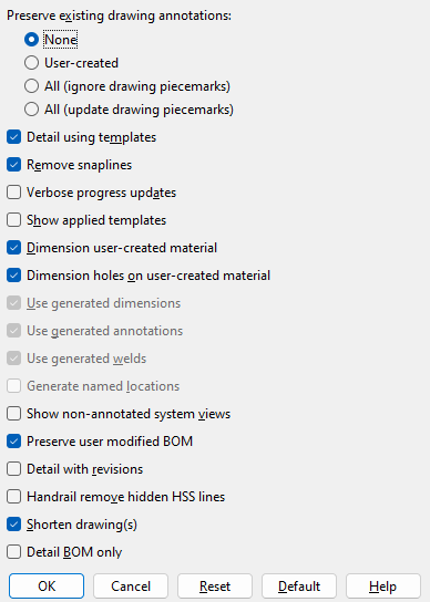
Preserve existing drawing annotations: None or User-created or All (ignore drawing piecemarks) . or All (update drawing piecemarks) .

' None ' permanently erases any changes you made in the Drawing Editor to the member details you are generating. All user-added drawing layers will be lost, as will any user-added graphics such as sheet items or images or symbols , or user-added lines , or user-added labels , or etc. If you deleted a system-generated drawing layer, that layer will be regenerated. The entirely new drawing will include all changes current in the model, including any system-added and user-created views that are listed on the view list in member isolation . The scale of the drawing will be the " Drawing scale " set on the Drawing Data window if the box for " Detail from drawing scale " is checked ( ) -- or else it will be the " Default member detail scale " or, if applicable, the " Default member detail scale by nominal size ."

' User-created ' causes user-created alterations to existing member details to be preserved in the new versions of those same member details you are now generating. User created annotations are additions of labels, dimensions, layers, etc., including objects added using Paste or Add Standard Detail . The auto detailing program will overlay any user annotations that you previously applied with automatically generated new dimensions, labels, weld, bevel and hole symbols, etc. The user-created annotations will remain on the layers that they were originally applied to. The auto detailing program will use mapping to avoid overwriting the user annotations wherever possible. The scale used is the " Drawing scale " set on the Drawing Data window. The shop bill will be updated with current quantities and piecemarks. Newly created views added in member isolation will be applied to the revised drawing. Make sure that you review all details that you have regenerated in this way to make sure that they are correct before you place them on a sheet. Warning: User-created drawing annotations will probably not be saved correctly if they were added to shortened member details. You should always Unshorten member details before adding annotations to them.

' All (ignore drawing piecemarks) ' causes both user-created alterations and system-generated annotations to be preserved in the new versions of the member details you are now generating. The only portion of the detail that will be regenerated is the material portion of each view -- the material polygons. Otherwise, the member detail will be detailed exactly as it was detailed previously. The shop bill will also be updated with current quantities and piecemarks and any bill information from a job standard detail added to the member's end will be preserved. Annotations on the drawing itself, such as dimensions, labels, weld, bevel, hole symbols and piecemarks, whether system- or user-generated, will not be changed. Newly created views added in member isolation will not be applied. The scale used is the " Drawing scale " set on the Drawing Data window. Be sure to review details generated in this way to make sure they are correct before you place them on a sheet.

' All (update drawing piecemarks )' does the same thing as the ' All (ignore drawing piecemarks) ' except that material marks called out on the member detail are updated along with the material polygons.

Note: Any of these three choices when you are generating member details for the first time will produce the same results.

Fabricator Setup: Home > Project Settings > Fabricator > Detailing Defaults > " Members " sets the choice (' None ' or ' User-created ' or ...) that is made here by default when a member is detailed for the first time. Changes made on this window are saved with the drawing(s) you selected before pressing " Settings " to open this window, but your changes to this window do not affect the window in Fabricator Setup . To repopulate this window with the defaults from Fabricator Setup , you can press the " Default " button.

page 1 | contents | detail members > select members > press settings | top


Detail using templates: or .

VIDEO Various options related to " Detail using templates " are available on the Member Annotations and Dimensioning window that opens when you Detail Members . (Recorded in SDS2 Detailing , v2015.)

VIDEO " Detail using templates " may get you better results when you auto detail certain custom members. This video shows the detail of a roof frame . (Recorded in SDS2 Detailing , v2016.)

Detail using templates
Using the default set of templates, detailing with or without templates generally produces the same results. To customize automatic detailing to deliver a desired content and appearance in a drawing, you can use custom templates.

If this box is checked ( ), then member detailing will apply templates that are stored in the fabs folder in your current Job . Any per-drawing setup overrides ( Settings > Drawing Settings ) that have been specified for a drawing that was selected to undergo detailing will be applied at this time. You also have options, on this window, for " Remove snaplines ," " Verbose progress updates " and " Show applied templates ."

If the box is not checked ( ), member detailing will be done without reference to the special instructions that are provided in templates.

Templates used for member detailing are, as mentioned above, stored in your current Job's fabs folder. The templates detailing program is permitted to select templates from both the fabs/default_templates folder and from templates associated with your current Fabricator . Where a name of a template file is the same in both sources, Detail Members will apply the template from the current Fabricator.

To change to a different Fabricator and thus give templates detailing access to that Fabricator's templates, you can press " Change Fabricator " on the SDS2 Setup Job or Fabricator Options window (the main setup menu).

Some Fabricators may not have templates. The Copy Detailing Templates utility can be used to copy a set of templates for use with a particular Fabricator. If a Fabricator does not have a set of templates, the fabs/default_templates folder will exclusively be used as the source file for templates detailing.

Fabricator Setup: Home > Project Settings > Fabricator > Detailing Defaults > " Members " sets the choice ( or ) that is made here by default when a member is detailed for the first time. Changes made on this window are saved with the drawing(s) you selected before pressing " Settings " to open this window, but your changes to this window do not affect the window in Fabricator Setup . To repopulate this window with the defaults from Fabricator Setup , you can press the " Default " button.

page 1 | contents | detail members > select members > press settings | top


Remove snaplines: or . This applies when you have chosen to " Detail using templates " ( ). Snaplines are construction lines that are generated, for positioning purposes, during automatic detailing

Remove snaplines
Remove snaplines

If this box is checked ( ), then snaplines are removed before the drawing is shortened, resulting in a cleaner, less cluttered look in the finished drawing.

If the box is not checked ( ), then snaplines that are placed for the aligning of drawing objects will not be automatically removed before the finished drawing is generated. Since snap lines impede shortening, one side effect of not removing them is that the drawing may not shorten properly.

Fabricator Setup: Home > Project Settings > Fabricator > Detailing Defaults > " Members " sets the choice ( or ) that is made here by default when a member is detailed for the first time. Changes made on this window are saved with the drawing(s) you selected before pressing " Settings " to open this window, but your changes to this window do not affect the window in Fabricator Setup . To repopulate this window with the defaults from Fabricator Setup , you can press the " Default " button.

page 1 | contents | detail members > select members > press settings | top


Verbose progress updates: or . This applies when you have chosen to " Detail using templates " ( ). Having verbose progress updates can sometimes help you to locate and troubleshoot potential template problems.

Since " Verbose progress updates " is checked in this example, the following extra information is shown:
( R) 0200_beam_hgrp_clip_osl_end

If this box is checked ( ), the progress bar window will display the name of each template as it is applied. Total detailing time may increase, but not significantly. For the most part, template names flash by very quickly -- too fast for a person to read them. However, if you can read a template's name, there may be a problem with that template. Detail Members may be stalling on the template because the template contains bad instructions. The template may require some debugging before it stops giving the auto detailing program problems.

If the box is not checked ( ), the progress bar for Detail Members will not show the name of each template as it is applied.

Fabricator Setup: Home > Project Settings > Fabricator > Detailing Defaults > " Members " sets the choice ( or ) that is made here by default when a member is detailed for the first time. Changes made on this window are saved with the drawing(s) you selected before pressing " Settings " to open this window, but your changes to this window do not affect the window in Fabricator Setup . To repopulate this window with the defaults from Fabricator Setup , you can press the " Default " button.

page 1 | contents | detail members > select members > press settings | top


Show applied templates: or . This applies when you have chosen to " Detail using templates " ( ).

The names of the templates that have been applied to a member detail are output as a label in the order in which they were applied. (R) stands for rotated. (U) stands for unrotated. The first number after the (R) or (U) is the priority. The (R) templates are listed first. Within the (R) and (U) listings, the templates are sorted (and applied) by priority.

If this box is checked ( ), then member detailing will generate a label (like the one shown above) which names the templates that have been applied to the drawing. This might be done to help you find the name of what template you want to select in order to change its Template Properties ( ) or to Display Rules .

If the box is not checked ( ), the names of the templates will not be automatically identified on the drawing. You can still find the name of the template that generated a particular object on the drawing by using Creating Rule ( ).

Fabricator Setup: Home > Project Settings > Fabricator > Detailing Defaults > " Members " sets the choice ( or ) that is made here by default when a member is detailed for the first time. Changes made on this window are saved with the drawing(s) you selected before pressing " Settings " to open this window, but your changes to this window do not affect the window in Fabricator Setup . To repopulate this window with the defaults from Fabricator Setup , you can press the " Default " button.

page 1 | contents | detail members > select members > press settings | top


Dimension user-created material: or . User-created material is material created in Modeling using Material options. System-created material is material generated during the solids creation phase of Process and Create Solids .

If this box is checked ( ), member detailing will generate dimensions on user-created material.

If the box is not checked ( ), only system-created material will be dimensioned on the member detail.

Fabricator Setup: Home > Project Settings > Fabricator > Detailing Defaults > " Members " sets the choice ( or ) that is made here by default when a member is detailed for the first time. Changes made on this window are saved with the drawing(s) you selected before pressing " Settings " to open this window, but your changes to this window do not affect the window in Fabricator Setup . To repopulate this window with the defaults from Fabricator Setup , you can press the " Default " button.

page 1 | contents | detail members > select members > press settings | top


Dimension holes on user-created material: or . User-created material is material created in Modeling using Material options. Holes can be created through such material using 3D Add Hole .

If this box is checked ( ), member detailing will dimension holes on user-created material as well as system-created material.

If the box is not checked ( ), holes will be dimensioned on system-created material only.

Fabricator Setup: Home > Project Settings > Fabricator > Detailing Defaults > " Members " sets the choice ( or ) that is made here by default when a member is detailed for the first time. Changes made on this window are saved with the drawing(s) you selected before pressing " Settings " to open this window, but your changes to this window do not affect the window in Fabricator Setup . To repopulate this window with the defaults from Fabricator Setup , you can press the " Default " button.

page 1 | contents | detail members > select members > press settings | top


Use generated dimensions: or .

If this box is checked ( ), member detailing will automatically dimension distances between holes, material edges and work points on the members that you select (in step 2 ).

If the box is not checked ( ), Detail Members will turn off its automatic dimensioning routines when it generates drawings of the members you select. Nonstandard edge distances will continue to be dimensioned.

Fabricator Setup: Home > Project Settings > Fabricator > Detailing Defaults > " Members " sets the choice ( or ) that is made here by default when a member is detailed for the first time. Changes made on this window are saved with the drawing(s) you selected before pressing " Settings " to open this window, but your changes to this window do not affect the window in Fabricator Setup . To repopulate this window with the defaults from Fabricator Setup , you can press the " Default " button.

page 1 | contents | detail members > select members > press settings | top


Use generated annotations: or .

If this box is checked ( ), member detailing will automatically add annotations such as labels, pointers, bevel symbols and weld symbols on the members you select (in step 2 ).

If the box is not checked ( ), Detail Members will turn off its routines for adding annotations when it generates drawings of the members you select.

Fabricator Setup: Home > Project Settings > Fabricator > Detailing Defaults > " Members " sets the choice ( or ) that is made here by default when a member is detailed for the first time. Changes made on this window are saved with the drawing(s) you selected before pressing " Settings " to open this window, but your changes to this window do not affect the window in Fabricator Setup . To repopulate this window with the defaults from Fabricator Setup , you can press the " Default " button.

page 1 | contents | detail members > select members > press settings | top


Use generated welds: or .

Use generated welds
Use generated welds

If this box is checked ( ), member detailing draws weld symbols on the detail that represent the 3D welds that appear in Modeling .

If the box is not checked ( ), Detail Members does not draw any weld symbols on the member detail. You will have to use Add Weld or Weld Combo or Add Standard Detail if you want weld symbols added to the drawing.

Fabricator Setup: Home > Project Settings > Fabricator > Detailing Defaults > " Members " sets the choice ( or ) that is made here by default when a member is detailed for the first time. Changes made on this window are saved with the drawing(s) you selected before pressing " Settings " to open this window, but your changes to this window do not affect the window in Fabricator Setup . To repopulate this window with the defaults from Fabricator Setup , you can press the " Default " button.

page 1 | contents | detail members > select members > press settings | top


Generate named locations: or . This applies when you auto detail without templates (" Detail using templates "). Member details generated using templates always include named locations .

A member detail . Each named location in this screen shot is marked with an X . The Mark Named Locations tool was used to mark the named locations. Unless you use such a tool, you will not be able to see any named locations on a drawing. When a sheet with a member detail on it is plotted, any named locations that happen to be on that drawing will not affect the appearance of the plotted sheet.

If this box is checked ( ), each resulting member detail will include named locations. These named locations will be invisible unless you use a template development tool such as Mark Named Locations or Nearest Names or Find Property .

If the box is not checked ( ), auto detailing of the member details will be faster. However, due to higher speeds produced by multi-core detailing, the speed difference may not be obvious.

Fabricator Setup: Home > Project Settings > Fabricator > Detailing Defaults > " Members " sets the choice ( or ) that is made here by default when a member is detailed for the first time. Changes made on this window are saved with the drawing(s) you selected before pressing " Settings " to open this window, but your changes to this window do not affect the window in Fabricator Setup . To repopulate this window with the defaults from Fabricator Setup , you can press the " Default " button.

page 1 | contents | detail members > select members > press settings | top


Show non-annotated system views: or . This option only applies to system views, not user created views. System views of members are created in Modeling when members are added. You can look at these views in member isolation . System views are the views that do not have " (user created) " after their names on the view list in member isolation. User created views are always included in the final drawing, regardless of the choice you make here.

If this box is checked ( ), member detailing includes all system views in the final drawing -- even those views that do not have any annotations or dimensions on them. For example: Check this box in order to have Detail Members draw the " TOP VIEW " of a stair on the final stair detail. That " TOP VIEW " will be drawn even if it does not have any dimensions or annotations on it.

If the box is not checked ( ), Detail Members preliminarily details all of the system views that Process has generated, but omits from the final drawing those system views which do not have any dimensions or annotations on them. For example, member detailing might omit the " TOP VIEW " of a stair from the final stair detail.

Fabricator Setup: Home > Project Settings > Fabricator > Detailing Defaults > " Members " sets the choice ( or ) that is made here by default when a member is detailed for the first time. Changes made on this window are saved with the drawing(s) you selected before pressing " Settings " to open this window, but your changes to this window do not affect the window in Fabricator Setup . To repopulate this window with the defaults from Fabricator Setup , you can press the " Default " button.

page 1 | contents | detail members > select members > press settings | top


Preserve user modified BOM: or . . When this option is checked ( ), auto detailing gives you a new capability that you did not have prior to v2018.

VIDEO

A new line is added to a member bill of material. The member is then re-detailed with " Preserve user modified BOM " turned on, thus preserving the line. When the member is re-detailed again, this time with " Preserve user modified BOM " turned off, the user-added line is removed. (Recorded in SDS2 Detailing , v2018.)


VIDEO

Selecting a bill of material cell then right-clicking outside of that cell brings up a context menu with a context-sensitive option of either " Preserve cell " or " Do not preserve cell ." The video shows that unpreserved information can be changed during auto detailing even when " Preserve user modified BOM " is checked. (Recorded in SDS2 Detailing , v2018.)


In this bill of material, PRESERVED and UNPRESERVED are user modified entries. The colors tell you what member detailing will do when the " Preserve user modified BOM " option is checked.

If this box is checked ( ), member detailing preserves user modified entries to member bills of material that are re-detailed unless those entries are shown -- in the bill editor cells for that member's detail -- in the UNPRESERVED color . Text in cells that are in the PRESERVED color is preserved by member detailing. All other text is updated to match the model.

If the box is not checked ( ), Detail Members deletes then updates all information in the bills of material of the details you selected before pressing " Settings " to open this window. Those bill(s) are updated with current quantities and piecemarks and dimensions and weights based on information in the model. All user-modified information is lost.

Also see: This option remains enabled when " Detail BOM only " is checked.

Fabricator Setup: Home > Project Settings > Fabricator > Detailing Defaults > " Members " sets the choice ( or ) that is made here by default when a member is detailed for the first time. Changes made on this window are saved with the drawing(s) you selected before pressing " Settings " to open this window, but your changes to this window do not affect the window in Fabricator Setup . To repopulate this window with the defaults from Fabricator Setup , you can press the " Default " button.

page 1 | contents | detail members > select members > press settings | top


Detail with revisions: or . This applies if you selected piecemarks (in step 2 ) that have already been placed on detail sheets. A revision chart is not required for you to get revision information. That information can be maintained in the Sheet Revision Chart Editor even if there is no revision chart. Also, automatic clouding of revision changes can be done without a revision chart.

Drawing: B_7
is on Sheet: B_7,
which has revision information.
Original sheet revision: 0
Incremented revision: 1

 
In step 5 of the Detail Members procedure, you will get a message like this one if one of the member details you are re-detailing is on a sheet with revision information.
This revision chart was automatically updated during Detail Members . Auto detailing entered the incremented "REV" and the "DATE" because the box for " Locked... " was checked in the revision editor for the sheet that the member being detailed was on.
" Detail with revisions " instructs Detail Members to draw clouds (on a revision layer of the member detail) around changes it finds. The character inside the delta symbol indicates the " Sheet revision " level.

If this box is checked ( ), member detailing clouds changes on the affected detail per the " Method to be used for clouding changes on details " and accounts for materials that are deleted from the bill of material based on " Modify bill of material ." It does the clouding by generating the new drawing, then comparing the new drawing with the base drawing , then generating clouds around areas that are different in the new drawing. The clouds and delta symbols are placed on a revision layer which can optionally be printed or not. On the sheet that the detail appears on, Detail Members enters the selected " Short revision description " to the "DESCRIPTION" column of the revision chart if the " Short revision description " has changed since the affected detail last underwent Detail Members . Member Detailing increments the revision (noted in the "REV" column of the chart) if the detail has changed in any way (including a status change) and if the box for " Locked... " is checked in Edit Revision Chart .

If the box is not checked ( ), Detail Members does not add any revision annotations to the detail. It also does not make any changes to the revision chart or to the bill of material (which appear on the detail sheet).

Steps for automatic revision tracking (one possible procedure):

Cycle 1
1 . " Disable automatic creation of BASE drawings " needs to be turned off in Sheet Revisions setup.
2 . Create a new sheet outline and Revision Chart > Place a revision chart onto it.
3 . Create a new detail sheet using the sheet outline you created.
4 . Detail a member and Sheet Items > Add it to the detail sheet that uses the outline you created.
5 . On the new detail sheet, Objects > Revision Chart > Edit , enter the chart's first line and set it to " Locked... " See the warning below.
6 . Make a change in Modeling that will affect the resulting member.
7 . detail the member again, and this time check the box for " Detail with revisions ."
8 . On the detail sheet, you will find that auto detailing clouded the changes to the member detail and added a new revision and date to the revision chart.
Cycle 2
9 . Objects > Revision Chart > Edit the entry that auto detailing made in step 7 above. Set the chart to " Locked... "
10 . Make a change in Modeling that will affect the resulting member.
11 . detail the member again, and this time check the box for " Detail with revisions ."
12 . On the detail sheet, you will find that auto detailing clouded the changes to the member detail and added a new revision and date to the revision chart.
Note : If " Disable automatic creation of BASE drawings " is turned on, you can still get auto detailing to cloud changes on drawings. However, you will need to manually Create Base Drawing yourself.

  delta symbol with a ? inside
Warning : If you don't enter a number or letter to the "REV" cell in the first line of the Sheet Revision Chart Editor before you " Detail with revisions ," Detail Members won't know if it needs to increment the revision using a letter such as A or a number such as 1. The delta symbol will show a "?" instead of a letter or a number. See step 5 in the procedure above.

Fabricator Setup: Home > Project Settings > Fabricator > Detailing Defaults > " Members " sets the choice ( or ) that is made here by default when a member is detailed for the first time. Changes made on this window are saved with the drawing(s) you selected before pressing " Settings " to open this window, but your changes to this window do not affect the window in Fabricator Setup . To repopulate this window with the defaults from Fabricator Setup , you can press the " Default " button.

page 1 | contents | detail members > select members > press settings | top


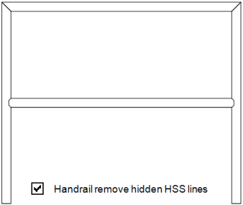
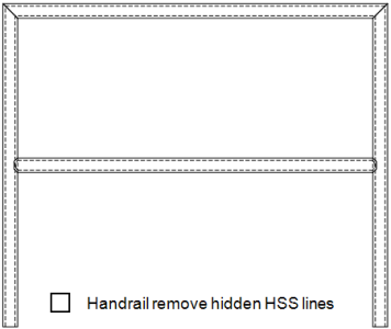
Handrail remove hidden HSS lines: or .

If this box is checked ( ), member detailing automatically does not include hidden lines on the details of the handrail member(s) that you select (in step 2 ). The hidden lines will be hidden from either pipe or HSS tube materials.

If the box is not checked ( ), member detailing automatically includes hidden lines on the details of the handrail member(s) that you select (in step 2 ). Tip : The hidden lines can manually be removed from the handrail drawing if this options is not checked.

Note: The option to removed the hidden HSS lines only applies to handrail members.

Fabricator Setup:Home > Project Settings > Fabricator > Detailing Defaults > " Members " sets the choice ( or ) that is made here by default when a member is detailed for the first time. Changes made on this window are saved with the drawing(s) you selected before pressing " Settings " to open this window, but your changes to this window do not affect the window in Fabricator Setup . To repopulate this window with the defaults from Fabricator Setup , you can press the " Default " button.

page 1 | contents | detail members > select members > press settings | top


Shorten drawing(s): or .

Shorten drawing(s)
Shorten drawing(s)

If this box is checked ( ), member detailing automatically shortens the details of the members that you select (in step 2 ). Shortening brings the two ends of the main material closer together so you get a better perspective of the connections on those two ends. The drawing is thus made more compact, and its essential elements are easier to read. Tip : If you choose this option, you should Unshorten each member detail before making graphical changes to it, then Shorten the member detail manually before you save it.

If the box is not checked ( ), the member is detailed in scale to its true proportions. Tip: If you choose this option, implement a procedure where you Open each member detail, make any graphical changes you want, then Shorten the member detail manually prior to using Sheet Item Add to place it onto a sheet or add it to another drawing.

Standard procedures: Before adding dimensions to a member detail that has been shortened, you need to Unshorten it to ensure that the newly added dimensions correctly measure the distances between points. It is also desirable to Unshorten prior to measuring with the Ruler or adding construction lines using BSCL . All drawing annotations need to be added in an unshortened view if you want to later be able to " Preserve existing drawing annotations ." You should Shorten a member detail prior to adding it to another drawing or sheet using Sheet Item Add .

Fabricator Setup: Home > Project Settings > Fabricator > Detailing Defaults > " Members " sets the choice ( or ) that is made here by default when a member is detailed for the first time. Changes made on this window are saved with the drawing(s) you selected before pressing " Settings " to open this window, but your changes to this window do not affect the window in Fabricator Setup . To repopulate this window with the defaults from Fabricator Setup , you can press the " Default " button.

page 1 | contents | detail members > select members > press settings | top


Detail BOM only: or . This option can be found only on the version of the Member Detailing and Annotations window that opens when you Process > Detail Current Piecemark . For Process > Detail Members ., the " Detail BOM only " check box has been moved [off of Member Detailing and Annotations ] to the member selection dialog .

If this box is checked ( ), auto detailing updates the member bill of material to match the model, but does not change the drawing. You may want to use this option instead of " Preserve existing drawing annotations " to update the bill while retaining labor-intensive work that you have done on a complicated drawing. Detail Members automatically marks for Plotting any sheets that contain bills of material that are affected. When this box is checked, you will find that all options on the Member Annotations and Dimensioning window except " Preserve user modified BOM " are disabled ( grayed out ).

If the box is not checked ( ), both the member bill of material and the drawing will be updated per changes in the model and applicable settings on the Annotations and Dimensioning window.

The default state of this check box is not checked ( ). Whenever you open a window on which " Detail BOM only " appears, the check box is always in the not checked state.

page 1 | contents | detail members > select members > press settings | top


To close the Member Annotations and Dimensioning window :

"OK" (or the Enter key) closes this window. Go to step 2 of Detail Members . In step 2, you choose the member(s) that you want to detail. The settings that you specified on this window will, when you press " OK ," be stored with whichever members(s) you selected before opening this window. This means that the next time you press the " Settings " button to open this window, you will see, on this window, the settings that were last specified for that detail.

"Cancel" (or the Esc key or the button) closes this window without saving any of the changes you have made to it.

"Reset" undoes all changes made to this window since you first opened it. The window remains open.

"Default" populates this window with the default settings specified in the " Members " section in Home > Project Settings > Fabricator > Detailing Defaults . The window remains open.

page 1 | contents | detail members > select members > press settings | top