"  Top Moment Plate " & " Bottom Moment Plate " connection design locks
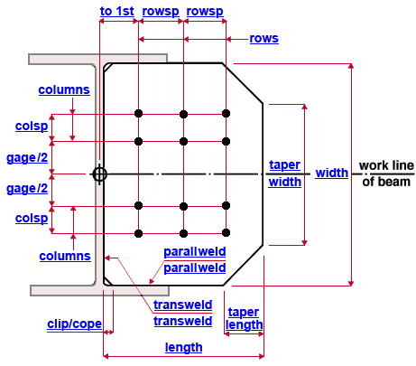
| Bolted moment flange plates can be designed for a beam to a column web (shown) or flange (not shown) per " |
|
||||
"  |
|
|||
Tip: When you lock (
) an enty in "
In general, connection design creates the top moment plate to match the bottom moment plate. The " Plate length " may be different on the two plates to accomodate sloping bolted moment connections.
Connection Guide: Click here or here . A bolted moment cap plate is a special case.
User Defined Connections: Settings that are locked (
Beam Edit: To change a setting, first set it to locked (
) may be updated, and the "
Connection design locks :
| Locks not dimensioned or called out on the drawing are marked ( not depicted ). |
![]() Top Moment Plate /
Top Moment Plate / ![]() Bottom Moment Plate
Bottom Moment Plate
Bolted moment flange plate
Plate length ( length ): The distance (parallel with the work line of the beam) between the edge of the moment flange plate that shop welds to the column and the edge opposite to that edge (see example ). If " Plate length " is unlocked (
Plate width ( width ): The distance (perpendicular to the work line of the beam) between the two edges of the bolted moment flange plate that are parallel with the work line of the beam (see example ). For a beam to a column flange, this is the length of the edge of the plate that shop welds to the column flange. For a beam to a column web, this is the pre-clipped or pre-coped length of the edge of the plate that shop welds to the column web. If " Plate width " is unlocked (
Plate thickness ( not depicted ): The " Material thickness " of the moment flange plate. Entering too small of a thickness may generate the end connection failure message " Locked flange plate thickness less than required for carrying moment ." Another connection failure that could result from too small of a thickness is " Base metal failure of flange weld ."
Corner clip/cope ( clip/cope ): Corner clips (or copes) are applied automatically at the two corners of a bolted moment flange plate edge that welds to the web of a column. The cuts are made so that the plate clears the web fillet (see example ). If " Corner operation for moment flange plates and column flange stiffeners " in Plate Design Settings is set to ' Cope ', then a cope is made instead of a clip. (see example ). The distance entered here is the distance (parallel with the work line of the beam) from the original corner of the plate (before it was cut) to the corner of the cut. ' 0 ' results in no corner clip or cope and is the default entry made if the bolted moment flange plate welds to a column flange.
Taper length: The distance (parallel with the work line of the beam) from one corner of either taper cut to the other corner of that same cut (see example ). Note that there are two taper cuts. The " Taper length " applies to each of these cuts. To remove a taper, set the " Taper length " to ' 0 ' and enter a ' Taper width ' that is equal to the ' Plate width '.
Taper width: The width of the plate edge that is opposite to (and parallel with) the plate edge that welds to the column (see example ). To remove a taper, enter a " Taper width " equal to the " Plate width " and set the " Taper length " to ' 0 '.
Flange bolts
Bolt diameter ( not depicted ): You can either type in any diameter (inches or mm), or you can select a bolt diameter from the combo box (
). The diameters that are listed in the combo box come from Home > Project Settings > Job > Bolt Settings > the " Available bolts " list. The bolt diameter entered here together with the " Hole type " set the diameter of holes the bolts go into. When " Bolt diameter " is unlocked (
Hole type ( not depicted ): Standard round or Short slot or Oversized or Long slot or User slot #1 or User slot #2 . The hole type selected here, together with the " Bolt Diameter " entered above, set the hole diameter.

Rows: The number of rows of bolts on the moment flange plate. Row spacing runs pallel with the work line of the beam. In the example above, the number of " Rows " is ' 3 '. If " Plate length " is unlocked (
Horizontal to 1st hole ( to 1st ): The distance (measured parallel with the work line of the beam) from the work point of the beam to the center of the first row of holes. In the example above, the beam's work point is at center of the column web. Changing the " Horizontal to 1st hole " moves the holes on the moment plate but does not change the plate length.
Horizontal hole spacing ( rowsp ): The row spacing. This is the distance (center to center) between any two adjacent rows of holes on the bolted moment plate (see example ). This distance is measured parallel with the work line of the beam. On a bolted moment flange plate, bolt column spacing runs parallel with the work line of the beam. If " Plate length " is unlocked (
Columns: Half of the total number of columns of holes in the moment plate. In other words, the total number of columns of holes on the near side or far side of the beam (see example ). Hole column spacing on a bolted moment flange plate runs perpendicular to the work line of the beam. In the example above, this number is ' 2 ' while the total number of columns of holes is ' 4 '. If " Plate width " is unlocked (
Vertical to 1st hole ( gage/2 ): Half the gage between the inside columns of holes on the moment flange plate. In other words, this is the distance (measured parallel with the plate width) from the work line of the beam to the center of the nearest column of holes. Since the moment plate is symmetrical around the work line of the beam whose flange it bolts to, the inside columns of holes on the moment plate are each the same distance (this distance) from the work line. See the example . Changing the " Vertical to 1st hole " distance moves the holes, but does not change the width of the plate.
Vertical hole spacing ( colsp ): The column spacing. This is the distance (center to center) between any two adjacent columns of holes that are on the same side (near side or far side) of the work line of the beam (see example ).This distance is measured parallel with the width of the bolted moment plate, perpendicular to the work line of the beam.
( beam to column flange )
Weld size ( not depicted ): The weld size for shop welding the bolted moment flange plate to the supporting column flange. Since the example shows a moment flange plate to a column web, this weld is not shown.
( beam to column web )
Transverse weld ( transweld ): The weld size for shop welding the bolted moment flange plate to the web of the supporting column. See the example .
Parallel weld ( parallweld ): The weld size for shop welding the length edges of the bolted moment flange plate to the flanges of the supporting column. This appears as an option only if the beam welds to a column web. It does not appear for beams to a column flange. See the example .

