 Concrete Pad Footing ( Modeling > F2 >
  Concrete > " Pad Footing" )
Tool summary :
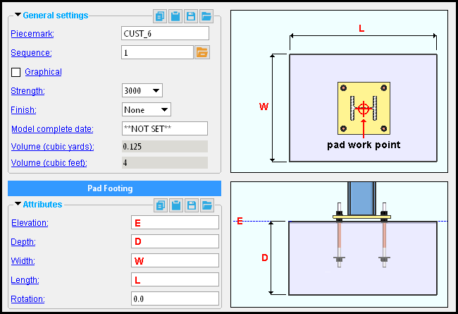
The Concrete Pad Footing Edit window :
|
To open this window :
- With the Default filter selected, double-click a concrete pad footing member.
- Add a concrete pad footing.
On this page :
Also see :
- Modeling (where a concrete pad footing can be added or edited)
- Rebar System (may be added to a pad footing)
- Rebar Area Layout (like Rebar System , except the user locates points to define the area)
concrete | F2 > concrete / rebar > | concrete pad footing | top
 To add a concrete pad footing :
|
A concrete pad footing can be added in Modeling by pressing F2 to open the Member Type Selection window, then double-clicking " Concrete Pad Footing ."
Concrete pad footings are typically added in a plan view . A single work point is required to locate the center of the top surface of the pad footing. The elevation of that work point sets the " Elevation " on the Concrete Pad Footing Edit window. The " Elevation " can be changed on the window, which opens immediately after the work point is located. You might, for example, use EXPT to locate the pad footing at the bottom of a column, then adjust the " Elevation " on the edit window.
Be aware that if you press " Cancel " on this window, the concrete pad footing will not be added, and the add operation will end.
After you press " OK " to close the Concrete Pad Footing Edit window when adding such a pad footing for the first time, you need to right-click ( Cancel ) in order to end the add operation.


mouse bindings If you have a Rebar System license, you can add a Rebar System to the concrete pad layout.
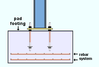
A 2-matt rebar system was added to this pad footing using the Rebar System custom component. Exact Point snaps to all four corners of a pad footing. INCM snaps to the point where a construction line or erection view line intersects the member line of a concrete pad footing. BSMB can base a construction line off of any side of the concrete pad footing member line .
concrete | F2 > concrete / rebar > | concrete pad footing | top
Elevation: The elevation (in the primary dimension " Units " or other units ) of the top surface of the concrete pad footing.
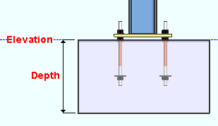
Tip: To determine the end elevation on a concrete pad footing in the 3D model, start up a tool such as Construction Line Add , select EXPT as the Locate option, snap the point location target to any of the four corners of the pad footing and reference the Z coordinate reported in the X-Y-Z display .
Depth: The distance (in the primary dimension " Units " or other units ) from the top surface of the concrete pad footing to the bottom surface of the concrete pad footing.

Changing the " Depth " causes the elevation of the bottom surface of the footing to be recalculated. It does not change the elevation of the top surface of the pad footing since the top elevation is always the " Elevation ."
Width: In a plan view , this is the length of either edge of the concrete pad footing that is vertical when the " Rotation " is ' 0 '.
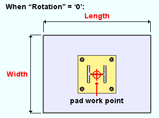
Length: In a plan view , this is the length of either edge of the concrete pad footing that is horizontal when the " Rotation " is ' 0 '.

Rotation: A positive or negative (-) number of degrees. A ' positive number ' rotates the concrete pad footing counterclockwise from the zero position that number of degrees. A ' negative (-) number ' rotates the concrete pad footing clockwise from the zero position.
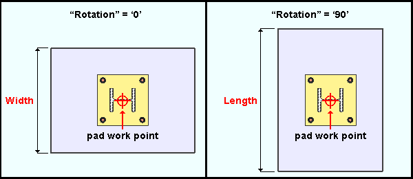
Rotation is around an axis that, in a plan view , is perpendicular to the work point of the concrete pad footing.
The zero position of the concrete pad footing is pad's orientation when its rotation is zero. When the concrete pad is in its zero position, its " Width " is vertical in a plan view.
concrete | F2 > concrete / rebar > | concrete pad footing | top


