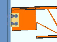
Flush Framed Clip Angle ("  Connection specifications " and more)
- Connection specifications:
- Locks:
Also see :
- Clip angle (index)
- Clip angle configurations (apply to beam and joist clip angles)
- Clip angle connections (Connection Guide)
- Setup of clip angle connections (index)
- Status Display ( Connection type > Clip angle ) (
 )
)
------"  Connection specifications " for joist ' Flush framed clip ' connections ------
Gage: Narrow gage or Wide gage or Heavy gage .
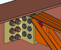
|
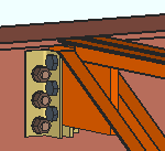
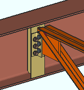
Heavy gage clip angles can have two columns of bolts. Here is an example of a bolted-bolted heavy gage double clip angle. |
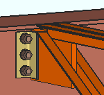
' Narrow ' specifies that a narrow gage clip angle connection be designed per the distance entered to Home > Project Settings > Fabricator > Standard Fabricator Connections > Clip Angle Settings > " Center to center distance, Narrow gage ." A narrow gage clip angle has a single column of bolts. Selecting ' Narrow ' also instructs connection design to use a clip angle size that is based on the " NM bolt diameter ." A ' Narrow ' clip angle's " Section size " is chosen per that non-moment bolt diameter in the Narrow Gage OSL All-Bolted Clip Angles or Narrow Gage OSL Bolted/Welded Clip Angles or Single Clip Angle Bolted OSL or Single Clip Angle All-Bolted or Single Clip Angle Welded OSL clip angle configuration (whichever configuration applies).
' Wide ' instructs connection design to create a wide gage clip angle per the distance entered to Home > Project Settings > Fabricator > Standard Fabricator Connections > Clip Angle Settings > " Center to center distance, Wide gage ." A wide gage clip angle has a single column of bolts. Selecting ' Wide ' also instructs connection design to use a clip angle size that is based on the " NM bolt diameter ." A ' Wide ' clip angle's " Section size " is chosen per that non-moment bolt diameter in the Wide Gage OSL All-Bolted Clip Angles or Wide Gage OSL Bolted/Welded Clip Angles clip angle configuration (whichever configuration applies).
' Heavy ' specifies double clip angles that may be shop welded or shop bolted. Heavy gage clip angles may have two columns of bolts per leg. The inside and outside center-to-center hole spacing of a heavy gage double clip angle is defined under Standard Fabricator Connections > Clip Angle Settings . Selecting ' Heavy ' also instructs connection design to use a clip angle size that is based on the " NM bolt diameter ." A ' Heavy ' clip angle's " Section size " is chosen per that non-moment bolt diameter in the Heavy Gage OSL All-Bolted Clip Angles or Heavy Gage OSL Bolted/Welded Clip Angles clip angle configuration (whichever configuration applies).
Also see: Clip Angle Configurations
Attachment to supported: Bolted or Welded . The supported member is the joist on whose edit window the ' Auto standard ' or ' User defined ' or ' Clip angle ' connection you are currently editing is applied as the left or right " Input connection type ."
|
|
|
|
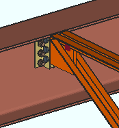
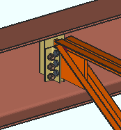
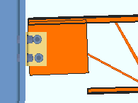
' Bolted ' specifies that connection design create a clip angle connection that bolts to the supported member (joist). The clip angle field bolts to the knife plate.
' Welded ' instructs connection design to create a clip angle that welds to the supported member (joist). The clip angle field welds to the knife plate.
Also see: Clip Angle Configurations
Attachment to supporting: Bolted or Welded . The supporting member is the beam or column that the outstanding leg(s) of the joist end's single or double clip angle connection attaches to.
|
|
|
|
' Bolted ' specifies that connection design create a clip angle connection that bolts to the supporting member (beam or column). The clip angle shop bolts to the member.
' Welded ' instructs connection design to create a clip angle that shop welds to the supporting beam or column. The clip angle shop welds to the supporting member.
Also see: Clip Angle Configurations
Side: Near side or Far side or Both .
| The left end of a joist | ||
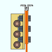
' Near side '
|
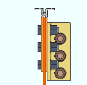
' Far side '
|
' Both '
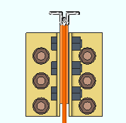
|
' Near side ' or ' Far side ' specifies the side of the joist's knife plate that the single clip angle fastens to. If the clip angle " Gage " is a choice other than ' Narrow ', the program resets the " Gage " to ' Narrow ' and will not let you change that gage. The clip angle will be designed per the Single Clip Angle Bolted OSL or Single Clip Angle All-Bolted or Single Clip Angle Welded OSL clip angle configuration (whichever configuration applies).
' Both ' specifies double clip angles: one fastened to the near side of the joist's knife plate, the other to the knife-plate's far side. The double clip angles will be designed per the Narrow Gage OSL All-Bolted Clip Angles or Narrow Gage OSL Bolted/Welded Clip Angles or Wide Gage OSL All-Bolted Clip Angles or Wide Gage OSL Bolted/Welded Clip Angles or Heavy Gage OSL All-Bolted Clip Angles or Heavy Gage OSL Bolted/Welded Clip Angles or All-Welded Attached to Supporting Clip Angles clip angle configuration (whichever configuration applies).
Near side versus far side: The near side is the side of the joist that faces you when its left end is to your left and its right end is to your right. The far side of the joist is the side that is opposite to the near side.
Also see: Clip Angle Configurations
Use erection bolts: Automatic or Yes or No . This applies when both " Attachment to supported " and " Attachment to supporting " are set to ' Welded '. In other words, it applies to all-welded clip angles.
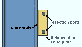
|
If " Use erection bolts " is set to ' Yes ' or possibly to ' Automatic ', an All Welded: Attached to Supporting Member double clip angle is provided with two erection bolts that field bolt the double clip angle to the knife plate of the supported joist. |
' Automatic ' specifies that connection design apply the choice at Home > Project Settings > Fabricator > PIecemarking > All-Welded Clip Angles > All-Welded Attached to Supporting Clip Angles > " Provide erection bolts ."
' Yes ' instructs connection design to design the welded-welded double clip angle connection with erection bolts to facilitate the field welding of the connection. The erection bolts are field bolts. The bolts are the "
Connection type " > " NM Bolt type " and " NM bolt diameter " that are specified for that joist connection's end. Two erection bolts are provided.
' No ' instructs connection design to design the welded-welded double clip angle without erection bolts.
Safety connection: Non-safety or Safety . This " ![]() Connection specifications " option applies to clip angles on two opposing joists on opposite sides of a supporting web (beam or column) so that the clip angle connections on both supported joists share bolts.
Connection specifications " option applies to clip angles on two opposing joists on opposite sides of a supporting web (beam or column) so that the clip angle connections on both supported joists share bolts.
' Non-safety ' lets all bolts be shared across the connected legs.
' Safety ' specifies that the clip angles be designed so that one bolt on each angle is shared by the joist and supporting member but not shared by the clip angle of the opposing joist. Whether the clip angles on a joist are vertically offset with respect to the angles on the opposing joist or staggered with respect to each other depends on the choice made to Home > Project Settings > Fabricator > Standard Fabricator Connections > Clip Angle Settings > " Safety connection angles ."
Stagger on: Neither or Supporting or Supported . This " ![]() Connection specifications " option applies when ' Bolted ' is selected for both the " Attachment to supported " and " Attachment to supporting " and angles are on ' Both ' sides of the joist.
Connection specifications " option applies when ' Bolted ' is selected for both the " Attachment to supported " and " Attachment to supporting " and angles are on ' Both ' sides of the joist.
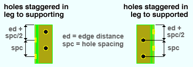
' Neither ' instructs connection design to create each angle in the clip angle connection with identical bolt spacing in both legs of the angle.
' Supporting ' places the first hole in the angle leg to the supporting member at the normal edge distance plus half the vertical spacing (" Vertical edge distance at ends " + [" Bolt spacing " / 2]).
' Supported ' places the first hole in the angle leg to the joist's knife plate at the normal edge distance plus half the vertical spacing (" Vertical edge distance at ends " + [" Bolt spacing " / 2]).
Project Settings: " Bolt spacing " is set per bolt diameter at Home > Project Settings > Fabricator > Detailing > Connection Erectability Settings . " Vertical edge distance at ends " is set at Home > Project Settings > Fabricator > Standard Fabricator Connections > Clip Angle Settings .
|
|
If this box is checked (
), connection design generates a built-up tee (two plates welded together) for the clip angles to bolt to. The check box for " Full depth extended tee " controls (for some framing situations) whether the tee will be designed to the depth of the connection or to the full depth of the supporting beam.
If the box is not checked (
), connection design bolts the clip angles to the supporting beam's web.
Full depth extended tee: ![]() or
or ![]() . This applies when -- here in "
. This applies when -- here in " ![]() Connection specifications " -- the box is checked for " Welded extended tee ."
Connection specifications " -- the box is checked for " Welded extended tee ."
|
|
If this box is checked (
), connection design creates a built-up tee that is the full depth of the supporting beam.
If the box is not checked (
), the built-up tee is designed to the depth of the connection if the top & bottom chords of the supported joist (this joist) are entirely below or entirely above the half-depth of the supporting beam. If the depth of the supported joist is greater than half the depth of the supporting beam, the built-up tee is designed to the full depth of the supporting beam.
Skew holes in angle: Automatic or Yes or No . This " ![]() Connection specifications " option applies to bolted clip angles on sloping joists.
Connection specifications " option applies to bolted clip angles on sloping joists.
|
|
' Automatic ' specifies that connection design apply the choice made to Home > Project Settings > Fabricator > Standard Fabricator Connections > Clip Angle Settings > " Skew holes in clip angles ."
' Yes ' instructs connection design to create clip angles with bolts skewed in the leg to the supported joist's knife plate so that the bolts run perpendicular to the joist's top and bottom chords.
' No ' instructs connection design to create clip angles with bolts that run parallel to the length of the angle.
Connection design locks :
Connection design locks for clip angle connections may appear, under a leaf with one of the below-listed names, on the Joist Edit window, or on a Connection Component window. The locks can also appear on the User Defined Connections window.
Connection Design Locks
(" Input connection type " = ' Flush framed clip ')Leaf Name Situation NS Clip FS Clip When you are looking at a joist whose left end is on your left, the joist's near side is the side you are facing. Knife Plate A flush framed clip angle (or shear plate) can be bolted or welded to the joist's knife plate. Welded Tee Connection design can create a built-up tee for beam- and joist-to-beam framing situations.
