Connection Guide : Clip Angles
| Disclaimer: This guide is not comprehensive. It shows only a few of the many clip angle connections that connection design can create. |
Also see :
- Clip angle connections (general information about)
- Connection design locks (to customize clip angles)
- Moment connections (connection guide -- includes clip angles)
- Status Display ( Connection type > Clip angle ) (
 )
)
- Ways of generating connections in Modeling (topics)
| Clip Angles for Offset Beam-to-Beam Framing | |
| Connection Design Locks = " NS Clip ," " FS Clip ," " Beam Web Doubler " | |
|
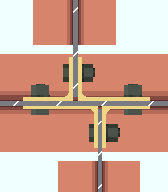
Input connection type: ' Clip angle ' or ' Auto standard ' or ' User defined '. |
| Comments: For offset, opposing beams, connection design automatically selects an angle from the " Preferred Angle Sizes " list that will carry the required gage. If no angle is found, the connection may be changed to a shear plate connection. | |
| Single Clip Angle to a Wide Flange Beam Flange | |
| Connection Design Locks = " NS Clip ," " FS Clip ," " Beam Web Doubler " | |
| Input connection type: ' Clip angle ' or ' Auto standard ' or ' User defined '. |
|
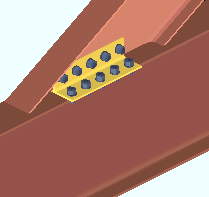
| Comments: Connection design can create clip angles on the end of a beam that slopes (but not skewed) to the flange of a wide flange beam. This can be done for wide flange, welded plate wide flange, S shape or channel beams. | |
| Clip Angles on a Sloping Beam to a Column | |
| Connection Design Locks = " NS Clip ," " FS Clip ," " Beam Web Doubler " | |
|
Input connection type: ' Clip angle ' or ' Auto standard ' or ' User defined '. |
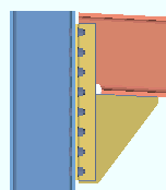
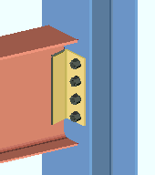
| Comments: Connection design can create clip angles on the end of a beam that slopes to a supporting column flange (as shown) or to a column or beam web. For these situations, there is a setup option to " Square cut ends of sloped beams ." | |
| Clip Angle on a Web-Horizontal Wide Flange Beam | |
| Input connection type: ' Clip angle ' or ' Auto standard ' or ' User defined '. |
|
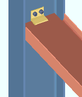
| Comments: Connection design can design clip angles on the end of a wide flange beam whose web is horizontal (" Beam rotation " = ' 90 ' degrees) if that beam frames to a column web or flange. | |
| Clip Angles Bolted to the Supported Beam | |
| Connection Design Locks = " NS Clip ," " FS Clip ," " Beam Web Doubler " | |

|
Input connection type: ' Clip angle ' or ' Auto standard ' or ' User defined '. |
| Settings: ' Wide gage ' (or ' Narrow gage '), ' Bolted ' (to supported) on ' Both sides ' of the beam web, ' Bolted ' (to supporting), staggered on ' Supporting '. | |
| Comments: Clip angles may connect a beam to a column, or to a beam. They can connect to the ' Supporting ' or Supported ' member. | |
| Bolted Clip Angles with Staggered Bolts |
| Connection Design Locks = " NS Clip ," " FS Clip ," " Beam Web Doubler " |
|
| Input connection type: ' Clip angle ' or ' Auto standard '. |
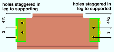
| Settings: ' Wide gage ' (or ' Heavy gage ' or ' Narrow gage '), ' Bolted ' (to supported) on ' Both sides ' of the beam web, ' Bolted ' (to supporting), staggered on ' Supporting ' (left end) and on ' Supported ' (right end). |
| Setup: Staggered bolts are optional for the following clip angle configurations: Heavy Gage OSL All-Bolted Clip Angles , Wide Gage OSL All-Bolted Clip Angles , Narrow Gage OSL All-Bolted Clip Angles , Single Clip Angles All-Bolted . |
| Clip Angles with Beam Web Doublers | |
| Connection Design Locks = " NS Clip ," " FS Clip ," " Beam Web Doubler " | |
|
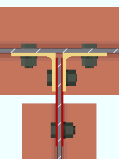
Required settings: ' If required ' must be selected for " Create web doublers ." |
| Comments: Depending on the " Shear " load on the beam, connection design designs one 3/16 inch thick web doubler on one side of the web, or two web doublers, one on each side of the web (shown in red). If doublers are not needed to prevent web buckling, they are not designed. For clip angles that weld to the supported beam, connection design welds the web doublers. | |
| Heavy Gage Clip Angles as Beam Splices | |
| Connection Design Locks = " NS Clip ," " FS Clip ," " Beam Web Doubler " | |
| Input connection type: ' Clip angle ' or ' Auto standard ' or ' User defined '.
|
|
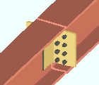
| Settings: ' Heavy gage ' (or other gage), ' Welded ' (to supported) on ' Both sides ' of beam web, ' Bolted ' (to supporting). | |
| Note: Heavy clips have two bolt columns. | |
| Clip Angle on One Side of Beam Web | |
| Connection Design Locks = " NS Clip " or " FS Clip " | |
|
|
Input connection type: ' Clip angle ' or ' Auto standard ' or ' User defined '. |
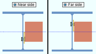
| Settings: ' Narrow gage ' (or ' Wide gage ') on the ' Near side ' (or ' Far side ') of the beam web. | |
| Clip Angles Shop Welded to the Supporting Member | |
| Connection Design Locks = " NS Clip ," " FS Clip ," " Beam Web Doubler " | |
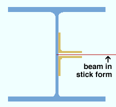
| Settings: ' Wide gage ' (or ' Narrow gage ') on ' Both sides ' of the beam web, ' Welded ' (to supporting). |
|
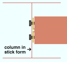
| Comments: This pair of clip angles is detailed with the column since they are shop welded to the column. Bolts to the beam are not shown since they are field bolts and the beam is in stick form. | |
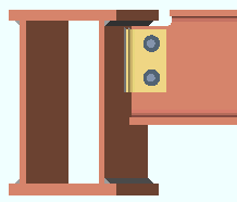
| Here's an example of clip angles that weld to a supporting welded plate box beam. Notice that connection design automatically copes the supporting beam so that it fits and is erectable. If the connection is not erectable, you get a " Cannot erect... " failure message. |
|
| Clip Angles Bolted (or Welded) to Supported Member | |
| Connection Design Locks = " NS Clip ," " FS Clip ," " Beam Web Doubler " | |
|
Settings: ' Wide gage ' (or ' Narrow gage '), ' Welded ' (or ' Bolted ' to supported), on ' Both sides ' of beam web, ' Bolted ' (to supporting).
|
| Comments: This pair of clip angles will be detailed with the beam if " Attached to " is set to ' Supported '. " Attached to " sets the shop attachement of the clip angle to the ' Supported ' or the ' Supporting '. | |
|
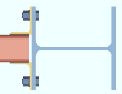
Clip angles welded to the supported HSS rectangular beam. You can get clip angles that weld (shown) or bolt (not shown) to a HSS rectangular beam, but not on a HSS round beam because of the material's curved surfaces. |
| Safety Clip Angles | |
| Connection Design Locks = " NS Clip ," " FS Clip ," " Beam Web Doubler " | |
| Input connection type: ' Clip angle ' or ' Auto standard ' or ' User defined '.
|
|
|
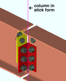
Settings: ' Wide gage ' (or ' Narrow gage ') ' Bolted ' (to supported) on ' Both sides ' of beam web, ' Bolted ' (to supporting) in a ' Safety ' configuration.
|
|
| Framing situations: Two beams framing on opposite sides of a supporting beam or column web. | |
| Setup: See " Safety Connection Angles ." | |
| Bottom Flange Cut for Safety Clip Angle | |
| Connection Design Locks = " NS Clip ," " FS Clip ," " Beam Web Doubler " | |
|
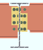
Settings: ' Wide gage ' (or ' Narrow gage '), ' Bolted ' (to supported) on ' Both sides ' of beam web, ' Bolted ' (to supporting) in a ' Safety ' configuration. |
| Setup: For connection design to design this connection, the box must be checked for " Extend connection and cut flange flush " in Clip Angle Settings . | |
| Clip Angle with Expanded Vertical Bolt Spacing | |
| Connection Design Locks = " NS Clip ," " FS Clip ," " Beam Web Doubler " | |
| Input connection type: ' Clip angle ' or ' Auto standard ' or ' User defined '. |
|
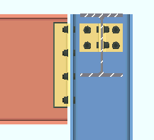
| Comments: If the box is checked for " Use expanded spacing ," connection design expands the spacing either 1.5 or 2 times the " Bolt spacing " that is set for the bolt diameter, in Connection Detailing/Fabricator Options . The " Moment type " must be set to ' Non-moment '. | |
| Clip Angle with Extended Welded Tee | |
|
Input connection type: ' Clip angle ' or ' Auto standard ' or ' User defined '. |
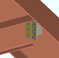
| Settings: " Welded extended tee " (checked) and " Full depth extended tee " (not checked). | |
| Design restrictions: Connection design creates the built-up tee to be the length of the clip angle only if both flanges of the supported beam are entirely below or entirely above (as shown) the half-depth of the supporting beam. | |
| Clip Angle with Full Depth Welded Tee | |
| Input connection type: ' Clip angle ' or ' Auto standard ' or ' User defined '. |
|
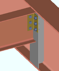
| Settings: " Welded extended tee " (checked). | |
| Framing condition: Wide flange or welded plate W or S shape or channel beam to a W or S or welded plate beam. Connection design creates the built-up tee to be the full depth of the supporting beam when the supported beam's depth is more than 1/2 the depth of the supporting beam. | |
| Clip Angle Extended Past Flange | |
| Connection Design Locks = " NS Clip ," " FS Clip ," " Web Extension Plate " | |
|
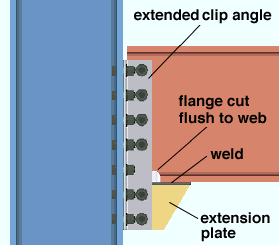
Settings: ' Wide gage ' (or ' Narrow gage ') ' Bolted ' (to supported) on ' Both sides ' of beam web, ' Bolted ' (to supporting) with web extended ' If required '.
|
| Comments: If the " Shear load " is sufficiently large and ' If required ' is selected for " Extend past flange ," connection design extends the clip angle past the flange. | |
|
|
Clip angle extended past the flange of a sloping beam. If ' If required ' had not been selected for " Extend past flange " in this situation, connection design would have failed the connection, resulting in a ' Plain end ' on the beam. In this example, the clip angle is ' Welded ' (to supported). |
|
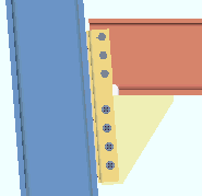
Extended clip angle welded to a sloping column. In this example, the clip angle is ' Welded ' to the supporting column.. Note that there is no bolt where the beam's flange is cut to allow the angle to extend past the flange. |
| Clip Angle Moment Connection | |
| Connection Design Locks = " NS Clip ," " FS Clip ," " Top Moment Plate ," " Bottom Moment Plate " | |
|
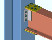
Framing situations: " |
| Also see: This connection guide has a separate section for moment connections. | |
| Clip Angles with a Safety Erection Seat | |
| Connection Design Locks = " NS Clip ," " FS Clip ," " Beam Web Doubler " | |
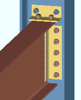
| Clip angle settings: Safety erection seats may be applied to ' Non-moment ' clip angle connections. |
|
| Erection seat settings: " Use a safety erection seat " (checked), " Location of safety erection seat " (' Top ' or ' Bottom '). | |
| Clip Angles on a Beam Framing to Nothing | |
| Connection Design Locks = " NS Clip ," " FS Clip ," " Beam Web Doubler " | |
|
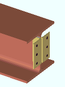
Comments: Unlike most connection types, clip angles can be applied on members that do not frame to anything. The same is true of end plates and bent plates and user base/cap plates . A search is available to help you locate members with indeterminate ends . |
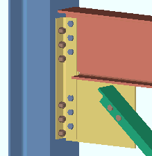
| Clip Angles Extended to a Vertical Brace Gusset Plate | |
| Connection Design Locks = " NS Clip ," " FS Clip " (beam), " NS/FS Clip Conn1 " (brace) | |
| Input connection type: ' Clip angle ' on the beam, ' Vbrc plate ' on the vertical brace. |
|
| Settings: ' Non-moment ', ' Both ' sides, " Combine beam/vbrc clip angles " (set to ' Yes '). | |
| Framing condition: Vertical brace framing to a beam and column. | |
|
|||||||||
