Connection Component Edit window ( Modeling )
 |
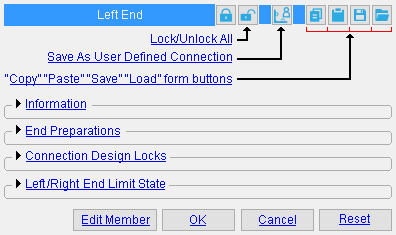
The Connection Component Edit window contains user-editable settings for system connections , which are connections that have been created by connection design . Member custom components (which are parametrically generated) should not be confused with connection components. |
| Note: The [ Left end ] banner shown above will read [ Right end ] if the component is on the right end of a member. A column's bottom end is its left end. Making changes to this window automatically updates equivalent settings on the left or right end of the member edit window. | |
To open the Connection Component Edit window :
|

|
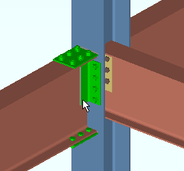
Method 1 : With the ' Connection Components ' filter or ' Default ' or ' All ' filter selected, double-click a system connection material to open the Connection Component Edit window for that connection. |

|
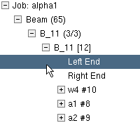
Method 2 : In the Model Tree , with " View By " set to ' Member Piecemark ' or ' Member Number ', double-click a member's " Left End " or " Right End ." The Connection Component Edit window opens for the system connection on that end of the member. Note: For a custom component , a listing is also provided in the Model Tree . That custom component's listing will be named after the custom component. It will not be named " Left End " or " Right End ." |
|
|
|
|
" Lock/Unlock All " |
||
![]() /
/ ![]() " Lock All Lockables" / "Unlock All Lockables "
" Lock All Lockables" / "Unlock All Lockables "
|
sets all "
End preparations " and "
Connection design locks " under " Left end settings " or " Right end settings " (as the case may be) to a locked state, thus preventing the connection from being altered by connection design . You will still be able to make changes to the connection by unlocking (
) particular lockable fields (so that connection design can make entries to that field) or by you yourself making different entries to the locked fields.
unlocks all connection design locks (lockables) associated with the left or right end (as the case may be). This results in a connection that is fully designed by connection design, without any user entries to connection design locks.
|
|
|
|
" Save As User Defined Connection " |
||
|
![]() " Save As User Defined Connection " is available as a button when you are editing one component at a time. It is not available (not visible) if you are editing multiple components .
" Save As User Defined Connection " is available as a button when you are editing one component at a time. It is not available (not visible) if you are editing multiple components .
The button allows you to save as a user defined connection changes that you have made to "
Connection design locks " and "
End preparations ." You can overwrite a previously saved user defined connection or create an entirely new user defined connection.
To overwrite a previously saved user defined connection:
1 . After you have set the "
Connection design locks " and "
End preparations " for this connection component, press the
button under " Left end settings " or its " Right end settings ."
2 . Select one of the user defined connections that are listed on the " Select One User Defined Connection " dialog. Press " OK ."
3 . On the yes-no dialog that opens, press " Yes " to overwrite the connection.

Overwrite existing user defined connection 'xxx'? 


4 . The user defined connection you selected will be overwritten with this connection component's settings.
To create an entirely new user defined connection:
1 . After you have set the "
Connection design locks " and "
End preparations " for this component, press the
button under " Left end settings " or " Right end settings ."
2 . Press the " New... " button.


to create a new user defined connection 3 . Type in the name that you want to give the new user defined connection, then press " OK ."
New user defined connection:
bm_udc_1 
4 . The new user defined connection you just created will store settings from this window.
|
|
|
|
" Copy " " Paste " " Save " " Load " |
||
![]() " Copy " " Paste " " Save " " Load " form buttons:
" Copy " " Paste " " Save " " Load " form buttons:
![]() Information ----------------------------------------------------------------------
Information ----------------------------------------------------------------------
If you are in a multi-user environment, a connection component edit window could be opened at the same time somebody else is adding a member that connects to that component's member. As a result, Process within member edit will be locked from accessing information about the component's member, and the following message will be generated:
| On-the-fly process failed |
If you are editing multiple connection components and the members those components belong to have different connection failed or connection-changed messages, a banner like the following is displayed:
| Multiple failed and/or changed connection messages |
The " Connection design locks set " banner notifies you that at least one setting in the connection is locked (
):
| Connection design locks set. |
|
Search: Connection design locks set
Status Display: Search > Connection design locks setA red end connection failed message like that shown below indicates a connection failure . Along with the failed message, you will find a
button for context-sensitive help about the message.
| Beam web shear capacity failed |
|
Connection failure messages by member type:
|
launches the User and Site Options > General > " Help browser " and gives you context-sensitive help about a connection failed message . If there is no connection failed message, this button will not be shown. A connection failed message may be generated, for example, when "
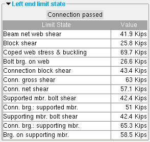
Left/Right End Limit State " analysis reveals that a connection cannot carry the load that the connection's member is subjected to. The various limit states associated with a connection are tested during connection design .
Report Writer: Member.LeftEnd.ConnectionHasFailed
Report Writer: Member.LeftEnd.MoreEnd.Conditions.ConnectionFailError
Advanced Selection: m.Ends[0].ConnectionHasFailed
Parametric module: m.Ends[0].ConnectionHasFailedA green " Connection changed ... " banner indicates connection design has deviated from the " Connection specification " settings entered by the user in order to make the connection work.
| Conn changed. Possibly: Angle vs Plate |
Search: Connections Changed by System .
Advanced Selection: m.Ends[0].DesignHasChanged
Parametric module: m.Ends[0].DesignHasChanged
Connection: Force and/or Graphical or a System connection .
|
|
|
|
|
|
|
' Force ' applies when the connection has failed , which results in your not getting any connection materials in the 3D model. To get connection materials so that you can review the situation and make needed changes, check the box for " ![]() Force ," then press " OK " (so that Create Solids is performed). The Connection Design Calculations report (and Expanded Connection Design Calculations ) will include a warning notifying the reader of that report that the connection has been forced.
Force ," then press " OK " (so that Create Solids is performed). The Connection Design Calculations report (and Expanded Connection Design Calculations ) will include a warning notifying the reader of that report that the connection has been forced.
|
|
|
|
|
|
' Graphical ' may have been automatically set to " ![]() Graphical " as a result of a user employing modeling operations to modify the system connection on this end of the member, thus making it graphical . A graphical connection will not be changed by connection design . On this window, you will not be able to change any of that connection's "
Graphical " as a result of a user employing modeling operations to modify the system connection on this end of the member, thus making it graphical . A graphical connection will not be changed by connection design . On this window, you will not be able to change any of that connection's " ![]() Connection design locks " or "
Connection design locks " or " ![]() End preparations ." The Connection Design Calculations report (and Expanded Connection Design Calculations ) will include the warning " GRAPHICAL CONNECTION -- STRENGTH CALCULATIONS NOT GENERATED ." If "
End preparations ." The Connection Design Calculations report (and Expanded Connection Design Calculations ) will include the warning " GRAPHICAL CONNECTION -- STRENGTH CALCULATIONS NOT GENERATED ." If " ![]() Graphical " is checked and you switch it to "
Graphical " is checked and you switch it to " ![]() Graphical " then press " OK " (so that Create Solids is performed), user-added modifications to that connection will be overwritten or erased. For example, user-added holes will disappear. On the General Information window for each of the connection materials, you will see that switching from "
Graphical " then press " OK " (so that Create Solids is performed), user-added modifications to that connection will be overwritten or erased. For example, user-added holes will disappear. On the General Information window for each of the connection materials, you will see that switching from " ![]() Graphical " to "
Graphical " to " ![]() Graphical " caused the connection materials that were regenerated to be changed from " User modified connection material " to " System created connection material ."
Graphical " caused the connection materials that were regenerated to be changed from " User modified connection material " to " System created connection material ."
Search and Change:
- Graphical Connections (a search)
- Change Graphically Altered to System Connections
- Change System to Graphically Altered Connections
- Change Force to System Connections
Status Display: Search > Graphical connections
Report Writer: Member.LeftEnd.MoreEnd.Settings.ForceConnection
Report Writer: Member.LeftEnd.IsGraphicalConnectionAdvanced Selection: m.Ends[0].ForceConnection
Advanced Selection: m.Ends[0].IsGraphicalConnectionParametric module: m.Ends[0].ForceConnection
Parametric module: m.Ends[0].IsGraphicalConnection
![]() End preparations ---------------------------------------------------------------
End preparations ---------------------------------------------------------------
|
Tip: If you " Save As User Defined Connections " from the Connection Component Edit window, end preparation settings will be included in the user defined connection.
To change an end preparation setting, first set it to locked ( ![]() ).
).
Top flange operation : ' None ' or ' Cope plain ' or ' Cope field weld #3 (Standard) ' or ' Cope shop weld #3 (Standard) ' or ' Cut flange width ' or ' Cut flange flush ' or ' Clip flange ' or ' Notch Top/Bottom ' or ' Notch near side/far side ' or ' Cope field weld #1 (FEMA) ' or ' Cope shop weld #1 (FEMA) ' or ' Clip web ' or ' Seismic cope field weld ' or ' Seismic cope shop weld '.
|
Some examples of the connection design lock sections that you might see on the Connection Component Edit window for a beam connection. |
![]() Left/Right end limit state ----------------------------------------------------
Left/Right end limit state ----------------------------------------------------

|
Limit states for a clip angle connection on the left end of a beam. The values shown represent the strength capacity of the connection or of the supported member (this beam) or of the supporting member. In this example, the connection passes. |
To close the Connection Component Edit window :
![]()
![]()
![]()
![]()
" Edit Member " does the same thing as " Cancel ," but also opens the member edit window associated with the connection component that you are editing.
" OK " (or the Enter key) closes the Connection Component Edit window and saves any changes you have made on the window to the member file of the affected member.
Solids on "OK": If the appropriate choice is made to User and Site Options > Modeling >" Automatically process after modeling operation ," then this member will automatically be regenerated ( Create Solids will take place) after your press " OK ." Otherwise, you will have to manually Process and Create Solids in order for changes you made on this window to be fully updated in the 3D model.
" Cancel " (or the Esc key or the
button) closes the Connection Component Edit window without saving any changes that you have made.
" Reset " undoes all changes made to this window since you first opened it. The window remains open.


