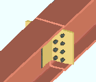
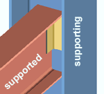
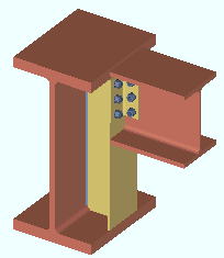
Clip Angle ("  Connection specifications " and more)
- Topics:
- Connection specifications:
- Locks:
Also see :
- Clip angle (index)
- Clip angle connections (Connection Guide)
- Setup of clip angle connections (index)
- Status Display ( Connection type > Clip angle ) (
 )
)
Design restrictions for clip angles :
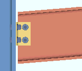
- Connection design is able to create clip angles on the ends of W or S or welded plate W or C or tube (HSS rectangular) beams in beam-to-beam or beam-to-column framing situations. The supported beam can be sloped or perpendicular to a wide flange or S shape or HSS rectangular or welded plate W or welded plate box column, but not to a HSS round column. If you specify a clip angle that welds/bolts to a pipe column or bolts to a tube or welded plate box column, connection design will change the clip angle to a single-plate shear connection.
- Connection design can also create a clip angle connection on a beam to the flange of a wide flange beam .
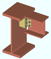
- Clip angles are applied on the end of the supported beam. They may optionally be detailed on (shop attached to) the supporting member (column or beam). If the beam frames to a tube or welded plate box column, the clip angle must be shop welded to the supporting column.
- " Moment " options can be applied to clip angle connections on W or S shape beams framing to a wide flange column web or flange or to a tube column.
- Clip angles can have a different " NM bolt type to supported " and " NM bolt type to supporting ."
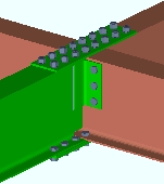
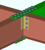
- Connection design looks to relevant setup options and clip angle " Connection specifications " to design an initial minimum setup connection. If necessary to meet the " Shear load " on the supported beam, connection design may increase bolt diameters, weld size, number of rows of bolts, or create web doublers.
Expressions that can be used for Advanced Selection to select beams with clip angles:
|
# Selects beams with auto standard clip angles on left end.
|
|
# Selects beams with auto standard clip angles on both ends.
|
|
# Selects beams with auto standard clip angles on both ends.
|
|
# Selects beams with auto standard clip angles on either end.
|
|
# Selects beams with welded clip angles, either end.
|
|
# Selects beams with conn specs set to narrow gage, either end.
|
"
|
Clip Angle Configuration |
" |
| All-Bolted | |
| Heavy Gage OSL | ' Heavy Gage ', ' Bolted ' (to supported), ' Bolted ' (to supporting), ' Supported ' (or ' Supporting ') |
| Wide Gage OSL | ' Wide Gage ', ' Bolted ' (to supported), ' Bolted ' (to supporting), ' Both ' (sides of web), ' Supported ' (or ' Supporting ') |
| Narrow Gage OSL | ' Narrow Gage ', Bolted (to supported), ' Bolted ' (to supporting), ' Both ' (sides of web), ' Supported ' (or ' Supporting ') |
| Single Angle | ' Narrow Gage ' (or ' Wide Gage '), ' Bolted ' (to supported), ' Bolted ' (to supporting), ' Near Side ' (or ' Far Side ' of web), ' Supported ' (or ' Supporting ') |
| Bolted/Welded | |
| Double Angle: Welded OSL | ' Narrow Gage ' (or ' Wide Gage '), ' Welded ' (to supporting), ' Bolted ' (to supported), ' Both ' (sides of web), ' Supporting ' (or ' Supported ') |
| Single Angle, Welded OSL | ' Narrow Gage ' (or ' Wide Gage '), ' Welded ' (to supporting), ' Bolted ' (to supported), ' Near Side ' (or ' Far Side ' of web), ' Supporting ' (or ' Supported ') |
| Heavy Gage OSL | ' Heavy Gage ', ' Bolted ' (to supporting), ' Welded ' (to supported), ' Supporting ' (or ' Supported ') |
| Wide Gage OSL | ' Wide Gage ', ' Bolted ' (to supporting), ' Welded ' (to supported), ' Both ' (sides of web), ' Supporting ' (or ' Supported ') |
| Narrow Gage OSL | ' Narrow Gage ', ' Bolted ' (to supporting), Welded (to supported), ' Both ' (sides of web), ' Supporting ' (or ' Supported ') |
| Single Angle, Bolted OSL | Narrow Gage ' (or ' Wide Gage '), ' Bolted ' (to supporting), ' Welded ' (to supported), ' Near Side ' (or ' Far Side ' of web), ' Supporting ' (or ' Supported ') |
| All-Welded | |
| Attached to Supporting Member | ' Welded ' (to supported), ' Welded ' (to supporting), ' Supporting ' (shop attached to) |
| Attached to Supported Member | ' Welded ' (to supported), ' Welded ' (to supporting), ' Supported ' (shop attached to) |
------" Connection specifications " for beam ' Clip angle ' connections ------
|
A beam's " |
Gage: Narrow gage or Wide gage or Heavy gage .
|
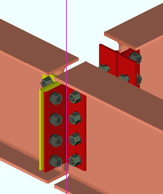
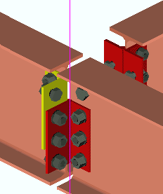
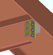
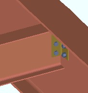
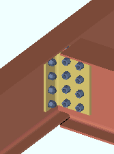
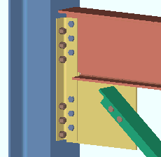
Heavy gage, welded clip angles can have two columns of bolts. In this example, heavy gage clip angles are used as beam splices. |
' Narrow ' specifies that a narrow gage clip angle connection be designed per the distance entered to Home > Project Settings > Fabricator > Standard Fabricator Connections > Clip Angle Settings > " Center to center distance, Narrow gage ." A narrow gage clip angle has a single column of bolts. Selecting ' Narrow ' also instructs connection design to use a clip angle size that is based on the " NM bolt diameter ." A ' Narrow ' clip angle's " Section size " is chosen per that non-moment bolt diameter in the Narrow Gage OSL All-Bolted Clip Angles or Narrow Gage OSL Bolted/Welded Clip Angles or Single Clip Angle Bolted OSL or Single Clip Angle All-Bolted or Single Clip Angle Welded OSL clip angle configuration (whichever configuration applies).
' Wide ' instructs connection design to create a wide gage clip angle per the distance entered to Home > Project Settings > Fabricator > Standard Fabricator Connections > Clip Angle Settings > " Center to center distance, Wide gage ." A wide gage clip angle has a single column of bolts. Selecting ' Wide ' also instructs connection design to use a clip angle size that is based on the " NM bolt diameter ." A ' Wide ' clip angle's " Section size " is chosen per that non-moment bolt diameter in the Wide Gage OSL All-Bolted Clip Angles or Wide Gage OSL Bolted/Welded Clip Angles clip angle configuration (whichever configuration applies).
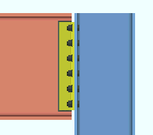
' Heavy ' specifies double clip angles that may be shop welded or shop bolted. Heavy gage clip angles may have two columns of bolts per leg. The inside and outside center-to-center hole spacing of a heavy gage double clip angle is defined under Standard Fabricator Connections > Clip Angle Settings . Selecting ' Heavy ' also instructs connection design to use a clip angle size that is based on the " NM bolt diameter ." A ' Heavy ' clip angle's " Section size " is chosen per that non-moment bolt diameter in the Heavy Gage OSL All-Bolted Clip Angles or Heavy Gage OSL Bolted/Welded Clip Angles clip angle configuration (whichever configuration applies).
Advanced Selection: m.Ends[0].Designed.IsWideGage
Advanced Selection: m.Ends[0].Designed.IsHeavyGage (also click here ).
Parametric module: m.Ends[0].Designed.IsWideGage
Parametric module: m.Ends[0].Designed.IsHeavyGage
Also see: Clip Angle Configurations
Attachment to supported: Bolted or Welded . The supported member is the beam on whose edit window the ' Auto standard ' or ' User defined ' or ' Clip angle ' connection you are currently editing is applied as the left or right " Input connection type ."
|
|
|
|
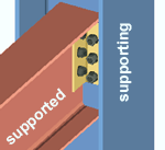
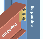
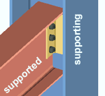
' Bolted ' specifies that connection design create a clip angle connection that bolts to the supported member (beam). If " Attached to " is ' Supported ', the clip angle shop bolts to the supported beam's web. If " Attached to " is ' Supporting ', the clip angle field bolts to the beam.
' Welded ' instructs connection design to create a clip angle that welds to the supported member (beam). If " Attached to " is ' Supported ', the clip angle shop welds to the supported beam's web. If " Attached to " is ' Supporting ', the clip angle field welds to the supported beam.
End connection failure message: Clip is not bolted to HSS beam with paddle plate
Also see: Clip Angle Configurations
Attachment to supporting: Bolted or Welded . The supporting member is the beam or column that the outstanding leg(s) of the beam end's single or double clip angle connection attaches to.
|
|
|
|
' Bolted ' specifies that connection design create a clip angle connection that bolts to the supporting member (beam or column). If " Attached to " is ' Supporting ', the clip angle shop bolts to the supporting member. If " Attached to " is ' Supported ', the clip angle field bolts to the supporting member.
' Welded ' instructs connection design to create a clip angle that shop welds to the supporting beam or column. If " Attached to " is ' Supporting ', the clip angle shop welds to the supporting member. If " Attached to " is ' Supported ', the clip angle field welds to the supporting member.
End connection failure message: Cannot erect the connection (beam clip angle welded to beam)
End connection failure message: Weld strength to supporting member exceeded
Also see: Clip Angle Configurations
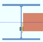
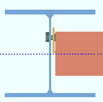
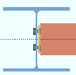
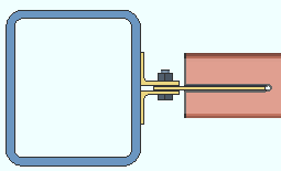
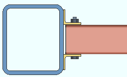
Side: Near side or Far side or Both .
' Near side '
|
' Far side '
|
' Both '
|
' Near side ' or ' Far side ' specifies the side of the beam's web that the single clip angle fastens to. If the clip angle " Gage " is a choice other than ' Narrow ', the program resets the " Gage " to ' Narrow ' and will not let you change that gage. The clip angle will be designed per the Single Clip Angle Bolted OSL or Single Clip Angle All-Bolted or Single Clip Angle Welded OSL clip angle configuration (whichever configuration applies).
' Both ' specifies double clip angles: one fastened to the near side web of the supported beam, the other to the far side web. The double clip angles will be designed per the Narrow Gage OSL All-Bolted Clip Angles or Narrow Gage OSL Bolted/Welded Clip Angles or Wide Gage OSL All-Bolted Clip Angles or Wide Gage OSL Bolted/Welded Clip Angles or Heavy Gage OSL All-Bolted Clip Angles or Heavy Gage OSL Bolted/Welded Clip Angles or All-Welded Attached to Supporting Clip Angles or All-Welded Attached to Supported Clip Angles clip angle configuration (whichever configuration applies).
Near side versus far side: The near side is the side of the supported beam's web that faces you when its left end is to your left and its right end is to your right. The far side of the web is the side that is opposite to the near side.
Advanced Selection: m.Ends[0].Designed.Side (also click here ).
Parametric module: m.Ends[0].Designed.Side
Also see: Clip Angle Configurations
Attached to: Supported or Supporting .
' Supported '
|
' Supporting '
|
' Supported ' specifies that connection design shop attach the clip angle connection to the supported beam. If " Attachment to supported " is set to ' Bolted ', the clip angle(s) shop bolt to the beam's web. If " Attachment to supported " is ' Welded ', the clip angle(s) shop weld to the beam. The connection is considered to be a submaterial of the beam and is selected (e.g., turns green ) when the beam is selected. The connection is considered to be a submaterial of the beam and will appear on details of the beam. A " Field clearance " can be applied.
' Supporting ' shop attaches the clip angle connection to the supporting member (beam or column). If " Attachment to supporting " is set to ' Bolted ', the outstanding legs of the clip angle(s) shop bolt to the supporting member. If " Attachment to supporting " is ' Welded ', the outstanding leg(s) shop weld to the supporting member. The connection is considered to be a submaterial of the supporting beam or column and will appear the detail of that member.
Advanced Selection: m.Ends[0].Designed.AttachToSupported (also click here ).
Parametric module: m.Ends[0].Designed.AttachToSupported
Also see: Clip Angle Configurations
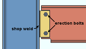
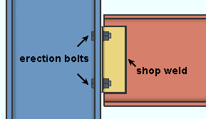
Use erection bolts: Automatic or Yes or No . This applies when both " Attachment to supported " and " Attachment to supporting " are set to ' Welded '. In other words, it applies to all-welded clip angles.
|
If " Use erection bolts " is set to ' Yes ' or possibly to ' Automatic ', an All Welded: Attached to Supporting Member double clip angle is provided with two erection bolts that field bolt the double clip angle to the web of the supported beam. |
|
If " Use erection bolts " is set to ' Yes ' or possibly to ' Automatic ', an All Welded: Attached to Supported Member double clip angle is provided with four erection bolts that field bolt to the supporting member (beam or column). Two of the four erection bolts are for the NS outstanding leg, the other two are for the FS OSL. |
' Automatic ' specifies that connection design apply the choice at Home > Project Settings > Fabricator > PIecemarking > All-Welded Clip Angles > All-Welded Attached to Supporting Clip Angles > " Provide erection bolts " if " Attached to " (on this window) is set to ' Supporting '. If " Attached to " is set to ' Supported ', then connection design applies the choice at All-Welded Attached to Supported Clip Angles > " Provide erection bolts ."
' Yes ' instructs connection design to design the welded-welded double clip angle connection with erection bolts to facilitate the field welding of the connection. The erection bolts are field bolts. For a beam end connection that is not auto standard, the bolts are the "
' No ' instructs connection design to design the welded-welded double clip angle without erection bolts.
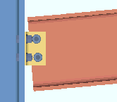
Safety connection: Non-safety or Safety . This " ![]() Connection specifications " option applies to clip angles on two opposing beams on opposite sides of a supporting web (beam or column) so that the clip angle connections on both supported beams share bolts.
Connection specifications " option applies to clip angles on two opposing beams on opposite sides of a supporting web (beam or column) so that the clip angle connections on both supported beams share bolts.
' Non-safety '
|
' Safety '
|
| The wide flange column in the above illustrations is shown in stick form so that its flange does not cover the connections on the beams that frame to its web. | |
' Safety ' specifies that the clip angles be designed so that one bolt on each angle is shared by the beam and column but not shared by the clip angle of the opposing beam. Whether the clip angles on a beam are vertically offset with respect to the angles on the opposing beam or staggered with respect to each other depends on the choice made to Home > Project Settings > Fabricator > Standard Fabricator Connections > Clip Angle Settings > " Safety connection angles ."
' Non-safety ' lets all bolts be shared across the connected legs.
Advanced Selection: m.Ends[0].Designed.SafetyConnection (also click here ).
Parametric module: m.Ends[0].Designed.SafetyConnection
Extend past flange: If required or Never . This " ![]() Connection specifications " option can apply to a clip angle on a beam framing to a column. Regardless of the choice made here, "
Connection specifications " option can apply to a clip angle on a beam framing to a column. Regardless of the choice made here, " ![]() Web Extension Plate " connection design locks are available. These locks have null values (distances of ' 0 ') if a web extehension plate is not required and when ' Never ' is specified.
Web Extension Plate " connection design locks are available. These locks have null values (distances of ' 0 ') if a web extehension plate is not required and when ' Never ' is specified.
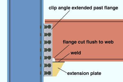
' If required ' specifies that connection design be permitted to create a connection using clip angles that are longer than the depth of the beam if the shear reaction on this end of the beam is sufficiently high. To do this, connection design cuts the lower flange flush to the web, extends the clip angles below the lower flange, and attaches them to a web extension plate.
' Never ' instructs connection design to fail the connection when the shear reaction is too high.
Clip angle steel grade: Connection design applies the steel grade selected at Home > Project Settings > Job > Design Settings > " Angle sections ."
Extension plate steel grade: Connection design uses the " Plate material grade " that is listed in Home > Project Settings > Fabricator > Standard Fabricator Connections > Plates > the " Web Extension Plates " section.
Advanced Selection: m.Ends[0].Designed.ExtendPastFlange (also click here ).
Parametric module: m.Ends[0].Designed.ExtendPastFlange
Connection design locks: "
Create web doublers: If required or Never .
|
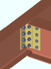
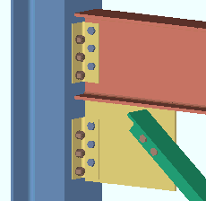
Web doublers may be generated for welded or bolted clip angles on thin webs subjected to sufficiently heavy loads. In this example, the doublers are generated (on both sides of the web) to compensate for a cope made to the web of the supported beam. The supported beam was coped to allow it to frame to the supporting beam. |
' If required ' specifies that connection design will, if necessary to meet loading conditions or compensate for copes in the beam's main material, create beam web doublers with a minimum thickness of 3/16 inch (5 mm). Connection design first tests a 3/16-inch doubler plate on one side. If the single doubler plate does not stand up to the load, connection design tries a 3/16 plate on both sides. If the two 3/16 plates still do not stand up to the load, connection design increases the thickness of the plates.
' Never ' instructs connection design to not generate beam web doublers. A connection may still be generated in the 3D model even though the connection would have failed due to its inability to stand up to block/net shear. For all connections with ' Never ' selected on the Beam Edit window, the message " Block/Net shear calcs are disabled " appears on the Beam Edit window.
Block/Net shear calcs. are disabled If you find the above message on the Beam Edit window or find that ' Never ' has been selected for an auto standard connection, be sure to check the Connection Design Calculations or Expanded Connection Design Calculations to make sure that connection has not failed. Selecting ' Never ' does not turn off the block/net shear checking that takes place when you generate a Design Calculations Report . Consequently, if the connection has failed, its failure is reported.
Tip 1: The Search option Beam Web Doublers or its counterpart Model > Status Display > Search > Beam web doublers can be used to find beams with web doublers in the 3D model.
Tip 2: When ' If required ' is selected, "
Advanced Selection: m.Ends[0].Designed.CreateWebDoublers (also click here ).
Parametric module: m.Ends[0].Designed.CreateWebDoublers
Stagger on: Neither or Supporting or Supported . This " ![]() Connection specifications " option applies when ' Bolted ' is selected for both the " Attachment to supported " and " Attachment to supporting " and angles are on ' Both ' sides of the beam web.
Connection specifications " option applies when ' Bolted ' is selected for both the " Attachment to supported " and " Attachment to supporting " and angles are on ' Both ' sides of the beam web.
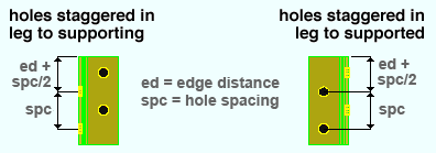
' Neither ' instructs connection design to create each angle in the clip angle connection with identical bolt spacing in both legs of the angle.
' Supporting ' places the first hole in the angle leg to the supporting member at the normal edge distance plus half the vertical spacing (" Vertical edge distance at ends " + [" Bolt spacing " / 2]).
' Supported ' places the first hole in the angle leg to the supported beam's web at the normal edge distance plus half the vertical spacing (" Vertical edge distance at ends " + [" Bolt spacing " / 2]).
Project Settings: " Bolt spacing " is set per bolt diameter at Home > Project Settings > Fabricator > Detailing > Connection Erectability Settings . " Vertical edge distance at ends " is set at Home > Project Settings > Fabricator > Standard Fabricator Connections > Clip Angle Settings .
Use expanded vertical bolt spacing: Automatic or Yes or No . This " ![]() Connection specifications " option can apply to a beam with clip angles to a beam or column so long as the " Moment type " is set to ' Non-moment ' in the beam end's "
Connection specifications " option can apply to a beam with clip angles to a beam or column so long as the " Moment type " is set to ' Non-moment ' in the beam end's " ![]() Moment " leaf.
Moment " leaf.
|
|

' Automatic ' specifies that connection design apply the choice made to Home > Project Settings > Fabricator > Standard Fabricator Connections > Clip Angle Settings > " Use expanded vertical bolt spacing ."
' Yes ' permits connection design to expand the vertical spacing of bolts to 1.5 times or 2 times the Home > Project Settings > Fabricator > Detailing > Connection Erectability Settings > " Bolt spacing " that is set per bolt diameter. The program may also adjust to a spacing other than 1.5 or 2 times the standard bolt spacing in order to accommodate piecemarking issues, loading conditions and unusual geometries.
' No ' instructs connection design to use the Home > Project Settings > Fabricator > Detailing > Connection Erectability Settings > " Bolt spacing " that is set per bolt diameter.
A possible application: When an axial load (" Tension " or " Compression ") has been entered on the end of a beam with a clip angle, expanded vertical bolt spacing can promote uniform loading across the bolts.
Another application: Expanded vertical hole spacing can also help to reduce fabrication costs by minimizing the number of rows of bolts in clip angles.
Advanced Selection: m.Ends[0].Designed.UseExpandedVerticalBoltSpacing (also click here ).
Parametric module: m.Ends[0].Designed.UseExpandedVerticalBoltSpacing
Welded extended tee: ![]() or
or ![]() . This "
. This " ![]() Connection specifications " option can apply to a wide flange, welded plate wide flange or channel beam with a clip angle connection framing perpendicular or sloping to a supporting beam.
Connection specifications " option can apply to a wide flange, welded plate wide flange or channel beam with a clip angle connection framing perpendicular or sloping to a supporting beam.
|
|
||||
| In these examples, the top of the beam frames to the supporting beam's top flange. You can also get a connection on a beam framing below the top flange. | |||||
If this box is checked (
), connection design generates a built-up tee (two plates welded together) for the clip angles to bolt to. The check box for " Full depth extended tee " controls (for some framing situations) whether the tee will be designed to the depth of the connection or to the full depth of the supporting beam.
If the box is not checked (
), connection design bolts the clip angles to the supporting beam's web.
Advanced Selection: m.Ends[0].Designed.WeldedExtendedTee (also click here ).
Parametric module: m.Ends[0].Designed.WeldedExtendedTee
Full depth extended tee: ![]() or
or ![]() . This applies when -- here in "
. This applies when -- here in " ![]() Connection specifications " -- the box is checked for " Welded extended tee ."
Connection specifications " -- the box is checked for " Welded extended tee ."
|
|
If this box is checked (
If the box is not checked (
Advanced Selection: m.Ends[0].Designed.FullDepthExtendedTee (also click here ).
Parametric module: m.Ends[0].Designed.FullDepthExtendedTee
Flange splice plates on: This member or Opposite member . For this " ![]() Connection specifications " option to be enabled (not grayed out), ' Bolted ' must be selected as the " Moment type " in this beam end's "
Connection specifications " option to be enabled (not grayed out), ' Bolted ' must be selected as the " Moment type " in this beam end's " ![]() Moment " leaf.
Moment " leaf.
|
|
' This member ' specifies that the moment flange splice plate be detailed with and shop bolted to the beam whose window this choice has been made to.
' Opposite member ' specifies that the moment flange splice plate be detailed with and shop bolted to the beam that is opposite to the beam whose window this choice has been made to.
Advanced Selection: m.Ends[0].Designed.FlangeSplicePlatesOn (also click here ).
Parametric module: m.Ends[0].Designed.FlangeSplicePlatesOn .
Replace doubler with larger clip: ![]() or
or ![]() . Web doublers may be generated for welded or bolted clip angles on thin webs subjected to sufficiently heavy loads when -- here in "
. Web doublers may be generated for welded or bolted clip angles on thin webs subjected to sufficiently heavy loads when -- here in " ![]() Connection specifications " -- ' If required ' is selected for " Create web doublers ."
Connection specifications " -- ' If required ' is selected for " Create web doublers ."
|
|
||||
| The angle used to replace the doubler (left) is an L8x4x1/2. The angle used with the doubler plate (right) is an L4x3 1/2x5/16. | |||||
If this box is checked (
If this box is not checked (
Advanced Selection: m.Ends[0].Designed.ReplaceDoublerWithLargerClip (also click here ).
Parametric module: m.Ends[0].Designed.ReplaceDoublerWithLargerClip
Use paddle plate: ![]() or
or ![]() . This applies when an HSS/TS beam frames to a column or a beam. It permits the design of bolted-bolted or bolted-welded clip angles. The option is disabled ( grayed out ) when -- here in "
. This applies when an HSS/TS beam frames to a column or a beam. It permits the design of bolted-bolted or bolted-welded clip angles. The option is disabled ( grayed out ) when -- here in " ![]() Connection specifications " -- the clip angle's " Attachment to supported " is set to ' Welded '.
Connection specifications " -- the clip angle's " Attachment to supported " is set to ' Welded '.
|
||||||
| The column's " Section size " can be an HSS/TS (shown) or a wide flange or etc., but cannot be a pipe (HSS round). Clip angles can also be designed for an HSS beam with a paddle plate to a beam. |
If this box is checked (
If this box is not checked (
End connection failure message: Clip is not bolted to HSS beam with paddle plate
Connection design locks: "
Skew holes in angle: Automatic or Yes or No . This " ![]() Connection specifications " option applies to bolted clip angles on sloping beams when the box is checked for Home > Project Settings > Fabricator > Detailing > Member Detailing Settings . > the " Beams " section > "
Connection specifications " option applies to bolted clip angles on sloping beams when the box is checked for Home > Project Settings > Fabricator > Detailing > Member Detailing Settings . > the " Beams " section > " ![]() Square cut ends of sloped beams ."
Square cut ends of sloped beams ."
|
|
' Automatic ' specifies that connection design apply the choice made to Home > Project Settings > Fabricator > Standard Fabricator Connections > Clip Angle Settings > " Skew holes in clip angles ."
' Yes ' instructs connection design to create clip angles with bolts skewed in the leg to the supported beam's web so that the bolts run perpendicular to the beam's flanges.
' No ' instructs connection design to create clip angles with bolts that run parallel to the length of the angle.
Advanced Selection: m.Ends[0].Designed.SkewHolesInAngle (also click here ).
Parametric module: m.Ends[0].Designed.SkewHolesInAngle
Combine beam/vbrc clip angles: Automatic or Yes or No . This " ![]() Connection specifications " option applies when this end of this beam has a clip angle connection and a vertical brace frames to this beam and to the same column that this beam frames to. In such a framing situation, connection design can create one or two pairs of clip angles.
Connection specifications " option applies when this end of this beam has a clip angle connection and a vertical brace frames to this beam and to the same column that this beam frames to. In such a framing situation, connection design can create one or two pairs of clip angles.
|
|
' Automatic ' specifies that connection design apply the choice made to Home > Project Settings > Fabricator > Standard Fabricator Connections > Clip Angle Settings > " Combine beam and vertical brace clip angles ."
' Yes ' instructs connection design to create a single pair of clip angles that connects both the beam and vertical brace gusset plate to the column. The clip angles use the " NM bolt diameter " and " NM bolt type to supported " and " NM bolt type to supporting " that are set for the beam.
' No ' instructs connection design to create two separate pairs of clip angles, one pair to connect the beam to the column, the other pair to connect the vertical brace gusset plate to the column.
Note: Connection design does not support connections on vertical braces connecting to a beam and column when the beam " Section size " is a channel.
Check supporting member for axial load: If required or For supporting column or For supporting beam or never . The " Supporting member web stress (T) " is reported as a " Left/Right end limit state " when a " Tension " load has been applied to the supported beam's clip angle connection end. This option affects whether or not that limit state is incorporated as a check within connection design that can potentially cause the clip angle connection to fail.
' If required ' results in design calculations 174 and 176 being potential causes of connection failure when applicable. Design calculation 174 is applicable when the clip angles on this end of the supported beam (this beam) have a " Tension " load applied to them and those clip angles attach to a supporting column's web. Calculation 176 is applicable when the clip angles on this end of the beam have a " Tension " load applied to them and the clip angles attach to the supporting beam's web.
' For supporting column ' results in calculation 174 being a potential cause of connection failure in the design of the clip angles on this end of the supported beam (this beam) when that end has a " Tension " load applied to it and the clip angles bolt to the supporting column's web. Calculation 176 will not result in connection failure of clip angles to a supporting beam's web, though the calculation will still be done, and a for-information-only note reporting the results of the calculation will be provided, when applicable, in both design calculations reports.
' For supporting beam ' results in calculation 176 being a potential cause of connection failure in the design of the clip angles on this end of the supported beam (this beam) when that end has a " Tension " load applied to it and the clip angles bolt to the supporting beam's web. Calculation 174 will not result in connection failure of clip angles to a supporting column's web, though the calculation will still be done, and a for-information-only note reporting the results of the calculation will be provided, when applicable, in both design calculations reports.
' Never ' results in calculations 174 and 176 still being performed, if applicable, but not ever causing the connection to fail. In the Connection Design Calculations or Expanded Connection Design Calculations , the results of the check will be reported with a parenthetical, for-information-only note such as " (For info. only, tension force that produces local support web stress of .9Fy (176) 5.5 kips ) ."
End connection failure message: Supporting web/flg overstressed by axial load .
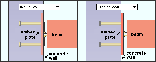
Embed plate location: Automatic or Inside wall or Outside wall . This " ![]() Connection specifications " option can apply when a beam frames to a concrete wall and the beam's " Input connection type " is ' Clip angle ' and an " Embed schedule entry " has been made in the "
Connection specifications " option can apply when a beam frames to a concrete wall and the beam's " Input connection type " is ' Clip angle ' and an " Embed schedule entry " has been made in the " ![]() Connection type " leaf. The option can also be found at Home > Project Settings > Job > Auto Standard Connections and at Home > Project Settings > Job > User Defined Connections .
Connection type " leaf. The option can also be found at Home > Project Settings > Job > Auto Standard Connections and at Home > Project Settings > Job > User Defined Connections .
|
| If you have a concrete license , you can also get a clip angle connection to an embed plate mounted inside or flush to a tilt-up panel . |
' Automatic ' instructs connection design to apply the choice made to Concrete Setup > Embed Schedule > " Plate location ."
' Inside wall ' embeds the plate in the concrete wall .
' Outside wall ' locates the plate flush to the wall.
Connection design locks :
Connection design locks for clip angle connections may appear, under a leaf with one of the below-listed names, on the Beam Edit window, or on a Connection Component window. For one special situation, noted below, you can find such locks on the Vertical Brace Edit window. The locks can also appear on the User Defined Connections window.
Connection Design Locks
(" Input connection type " = ' Clip angle ')Leaf Name Situation NS Clip FS Clip When the left end of a beam is on your left, web near side is the web view you are facing. Beam Web Doublers Beam web doublers are designed for beam-to-beam framing situations when required unless ' Never ' is selected for " Create web doublers ." Web Extension Plate Connection design may extend clip angles past the flange when " Extend past flange " is selected. Welded Tee Connection design can create a built-up tee for beam-to-beam framing situations. Safety Seat May be applied for non-moment clip angles in beam-to-column framing situations. Under " Top Moment Plate Bottom Moment Plate Under " Top Moment Angle Bottom Moment Angle The " Connection material " specified must be angle and suitable angle material must be available. Moment Cap Plate A beam with a welded moment connection to the top of a column flange. The moment cap plate shop welds to the column. Column Web Doublers
Column Flange StiffenersThe boxes for " Design for doublers " and " Design for stiffeners " are checked. All fields will be zero if doublers/stiffeners are specified but not required. NS/FS Clip Conn1
(vertical brace)For field bolting a vertical brace gusset plate to a column for a vertical brace to beam & column when the beam has an clip angle.

