Assembly Edit ( Modeling )

Tool summary :

  • Opens a selection dialog. On that dialog, select the assembly that you want to edit. The program opens that assembly in the Assembly Editor .
  • To review or edit additional assemblies while you are in the Assembly Editor , use File > Open .
  • See the step-by-step instructions .

Also see :

VIDEO

In the Assembly Editor . File > Save is used to save an assembly, a built-up tee. After Model > Assembly > Add to add the assembly in Modeling , Model > Assembly > Edit reopens the Assembly Editor for editing the specific assembly that the user selected. (Recorded in SDS2 Detailing , v2015.)


VIDEO

In the Assembly Editor , File > Save As saves an assembly, a built-up tee that includes materials and welds, under the same name as an assembly that is already in Modeling . Only those materials that the user selects are saved. After Model > Assembly > Add to add the assembly in Modeling , Model > Assembly > Edit reopens the Assembly Editor . The narrator uses View > Relative Depth to move 1 1/2 inch above the surface of the top edge of the built-up tee, then uses File > Save and the point locator INCL to modify the reference point of the assembly. The old assembly is then deleted in Modeling , and the new assembly is added. Since holes in the assembly are flush to member main material on a non-miscellaneous member (a beam in this video), Process and Create Solids automatically matches holes and adds bolts. (Recorded in SDS2 Detailing , v2015.)

page 1 | contents | model > assembly > | assemblies | top


   Step-by-step instructions :

1 . In Modeling , invoke Assembly Edit using any one (1) of the following methods:

Method 1 : Click the Assembly Edit icon, which is pictured above. The icon can be taken from the group named ' Model -- Assembly ' and placed on a toolbar (classic) or the ribbon (lightning).

Method 2 : If " Modeling layout style " is ' Classic ', you can use the menu system to choose Model > Assembly > Edit .

Method 3, 4 or 5 : Assembly Edit can also be configured to be invoked using a keyboard shortcut , the context menu , or a mode . For the lightning interface, this configuration is done using Customize Interface .

2 . The Select One Assembly selection dialog opens. On it is a list of all assemblies in your current Job .

 assembly_1
 assembly_2
 assembly_3
 assembly_4
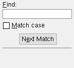
Typing characters to " Find " selects the assembly that begins with those characters. Pressing Enter closes this dialog and opens the selected assembly.

2a : Double-click the listing of one assembly that you want to open.

3 . The selection dialog closes, and your computer screen redraws to show the assembly that you selected in step 2. The view of the assembly is the view that was current when the reference point of the assembly was located, for example, by doing a Model > Assembly > Save in Modeling or File > Save As in the Assembly Editor . The toolbar configuration that is loaded is the choice made to User and Site Options > Toolbars > Detailing Station > " Assembly editor " or the Modeling Station " Assembly editor ." Here are some of things you can do to the assembly you just opened:

  • Add Material . You don't have to select a member when you add the material. The assembly member is automatically selected as the member that materials will be added to, thereby making those materials assembly materials.
  • You can perform operations such as Add Hole or Add Bolt or Add Weld or cut and fit operations found on the Model > Material window to any of the materials that attach to the assembly member , thus modifying the assembly.
  • You can Edit > Delete materials, bolts, holes or welds. Doing this for items that attach to the assembly member will remove those materials, bolts, holes or welds from the assembly.
  • You can Edit > Edit materials, bolts, holes or welds. Doing this for items that attach to the assembly member will remove those materials, bolts, holes or welds from the assembly.
  • You can switch to or from a plan view or elevation view , then File > Save to locate a reference point. The locating of the reference point establishes the view that is used for Add Assembly operations and also the view that you will see when you later File > Open that same assembly.
  • You can use File > Save Assembly As to rename the assembly you are editing.

page 1 | contents | model > assembly > | assemblies | top