 Precast Double Tee ( Modeling > F2 >
  Concrete > " Precast Double Tee" )
Tool summary :
The Precast Double Tee Edit window :

|
To open this window :
- With the Default filter selected, double-click a precast double tee member.
- Add a precast double tee .
On this page :
Also see :
- Modeling (where a precast double tee can be added or edited)
![]() To add a precast double tee :
To add a precast double tee :
|
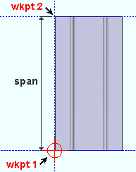
Two points locate the workline and span of a precast double tee. It does not matter which point you locate first. The left end (origin) of the member is independent of the order in which you locate the points. If both work points are at the same " End elevation " (same global Z coordinate ) and the member's " Rotation " is zero, the precast double tee is flat, with its top surface at that elevation . If the two work points are at different elevations, the precast double tee is sloping. |
A precast double tee should be added in a plan view .
A precast double tee can be added in Modeling by pressing F2 to open the Member Type Selection window, then double-clicking " Precast Double Tee ."
For more information related to locating the work points for a precast double tee member, familiarize yourself with the following help topics: Offset Controls for point location , Locators , Locate menu, point location target (
), status line , X-Y-Z display , global coordinate system .
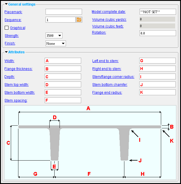
To adjust the " Width ," you can change the " Left end to stem " " Stem spacing " and " Right end to stem ." You cannot change the " Width " directly.
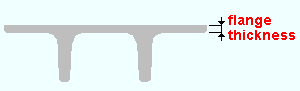
Flange thickness: Assuming that " Rotation " is set to ' 0 ' and the precast double tee is not sloping, this is the vertical distance (in the primary dimension " Units " or other units ) from the top surface of the precast double tee to the bottom surface of the precast double tee's top flange.
Adjusting the " Flange thickness " repositions the bottom surface of the precast double tee's flange. The top surface of the flange is not affected.
Depth: Assuming that " Rotation " is set to ' 0 ' and the precast double tee is not sloping, this is the vertical distance (in the primary dimension " Units " or other units ) from the top surface of the precast double tee to the bottom of the double tee stems.
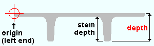
Adjusting the precast double tee " Depth " changes the depth of the double tee stems.
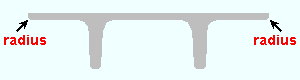
Stem top width: This applies to both stems of the precast double tee. Together with the " Stem bottom width ," it establishes the taper of the stems. This is the " D " dimension that is shown in the illustration at the top of this page.
Stem bottom width: This applies to both stems of the precast double tee. Together with the " Stem top width ," it establishes the taper of the stems. This is the " E " dimension that is shown in the illustration at the top of this page.
Stem spacing: Assuming that " Rotation " is set to ' 0 ' and the precast double tee is not sloping, this is the horizontal distance (in the primary dimension " Units " or other units ) between the two double tee stems.
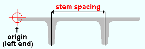
The two stems of a precast double tee have the same dimensions. Consequently, the spacing between these two stems can be measured center-to-center or left-edge-to-left-edge or right-edge-to-right-edge with the same result. Center-to-center dimensioning is shown in the above example.
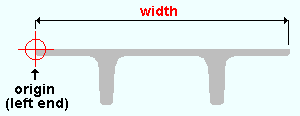
Left end to stem: Assuming that " Rotation " is set to ' 0 ' and the precast double tee is not sloping, this is the horizontal distance (in the primary dimension " Units " or other units ) from the member line edge of the precast double tee to the center of the leftmost stem.
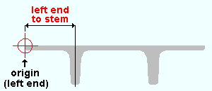
If, as in the example shown above, you are looking at the left end of the precast double tee in elevation, the origin symbol that appears when you hover the member marks the leftmost point of the top surface of the tee.
Right end to stem: Assuming that " Rotation " is set to ' 0 ' and the precast double tee is not sloping, this is the horizontal distance (in the primary dimension " Units " or other units ) from the edge opposite to the member line edge of the precast double tee to the center of the rightmost stem.
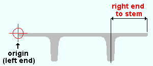
If, as in the example shown above, you are looking at the left end of the precast double tee in elevation, the origin symbol that appears when you hover the tee marks the leftmost point of the top surface of the tee. The "right end" of " Right end to stem " is the rightmost point of the top surface of the tee.
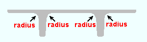
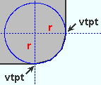
Stem/flange corner radius: A distance in the primary dimension " Units " or other units .
|
" Stem/flange corner radius " applies to all four stem/flange corners. |
|
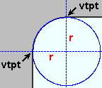
Vertical and horizontal construction lines at the vertex points ( vtpt ) of the rounded stem/flange corner meet at the center point of a construction circle whose " Radius " is equal to the " Stem/flange corner radius ." |
' 0 ' results in sharp stem/flange corners.
' A distance greater than 0 ' results in radiused stem/flange corners as described above.
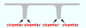
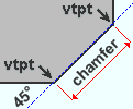
Stem bottom chamfer: The distance (in the primary dimension " Units " or other units ) from one vertex point of the 45-degree corner cut to the other vertex point. Each instance of this cut is applied to a corner at the bottom of each of the two stems.
|
" Stem bottom chamfer " applies to both bottom corners of each of the two stems. |
|
The " Stem bottom chamfer " distance is the chamfer dimension shown in this illustration. The abbreviation vtpt stands for vertex point . |
' 0 ' results in sharp, 90-degree corners at the bottom of each stem.
' A distance greater than 0 ' results in a 45-degree cut at the bottom corners of the stems as described above.
Flange end radius: A distance in the primary dimension " Units " or other units .
|
" Flange end radius " applies to both bottom corners of the flange. |
|
Vertical and horizontal construction lines at the vertex points ( vtpt ) of the rounded flange corner meet at the center point of a construction circle whose " Radius " is equal to the " Flange end radius ." |
' 0 ' results in sharp corners at the bottom of the flange.
' A distance greater than 0 ' results in radiused corners as described above.
|
|
------ ![]() Member ------
Member ------
End elevation: The elevation (in the primary dimension " Units " or other units ) of the work point at this end of the precast double tee. For a non-sloping double tee, both the left and right end elevations are the same.
|
|
| A precast double tee has two exact points , whose elevation you can change by changing the member's left- and/or right-end " End elevation ." |
|
|
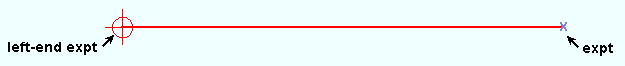
To determine the end elevation on a precast double tee in the 3D model , use Construction Line Add or a similar tool, select EXPT as the Locate option, then snap the point location target to the work point at the end of the member. The Z coordinate reported in the X-Y-Z display tells you the elevation at the snapped-to exact point.

