Step 3: Constructing a 3D Model

On this page :

Also see :

page 1 | contents | overview


Introduction :

  • Once you have opened a view in Modeling , you can create a 3D model of the building or structure that you will later generate detail drawings for. The types of members that you can use to create the 3D model are beams, columns, horizontal braces, vertical braces, girts, purlins, miscellaneous members and stairs. You add these members while in views.
  • As you build your 3D model, you will need to create views at various locations in order to add members. Views added using Add Grid Line ( ) are automatically given names and saved for future access. Other views, such as plan views created using Plan View ( ) or isometric views created using Isometric View ( ) are only temporary, unless you give them names and save them permanently by using Save View As . Any view that you save into a permanent, named file later be regenerated as a 2D design drawing or erection plan (using Detail Erection Views ).

page 1 | contents | overview | top


Reference drawings :

  • If you have in your possession a design drawing in the form of a .dxf , .dxb , .dwg , .dgn or .pdf drawing, you can convert that drawing into a reference drawing which can be used as a template for the layout of members or erection views in Modeling .
  • To convert the drawing, use Drawing Conversion . The original .dxf, .dxb, .dwg or .dgn drawing will be unchanged, but a copy of that drawing will be converted into a reference drawing.
  • After converting the drawing, you should probably start up the Drawing Editor and confirm that the drawing is correct. You may also want to File > Verify Reference Point to adjust the insertion point that you will be using to place the drawing in Modeling .

page 1 | contents | overview | top


Start up Modeling :

  • Home > Launch Modeling ( ).
  • If you are in a newly created Job with no erection views, and you are prompted to enter the name and elevation of a new erection view, then brings you into a plan view at that elevation. Otherwise, select a view from the list of already created views.

page 1 | contents | overview | top


Before laying out members :

Create a plan view of every floor in the structure that you are modeling.

YouTube video: Instead of Open View , you can double-click a grid line bubble to open the erection view that is associated with that grid line . (Recorded in SDS2 Detailing , v2020i)
  • Beams, columns and horizontal braces are easiest to lay out in a plan view . The top flange of a beam laid out in a plan view using INCL ( ) is placed at the elevation of that view.
  • You can create permanent plan views -- which you can later Open ( Ctrl + o ) -- by using Plan View ( ) followed by Save View As . Generally it is a good idea to name plan views for the elevation they are at. For example, name the plan view "100-0" if it is for the floor which is at an elevation of hundred feet.

If you imported a reference drawing that was a plan view, you may at this time wish to add that drawing.

  1. Open ( Ctrl + o ) the view (created in the previous step) that is at the elevation of the reference drawing that you want to add.
  2. Choose Model > Reference Drawing > Reference Drawing Tools , then press the " Add " button. Place the view at the appropriate location.

Lay out construction lines for placement of grid lines:

YouTube video: When open Modeling for the first time in a new project, you'll find a pair of construction lines that intersect at the 0, 0 point at your current elevation. This video shows how to add a grid of construction lines using BSCL. A reference drawing is used as a guide for construction line placement . (Recorded in SDS2 Detailing , v2020i)

Lay out grid lines (erection views) to provide INCL points for member work point layout in plan views.

YouTube video: Grid lines are added in a plan view by locating points at intersections of construction lines. New Erection View options are explained . (Recorded in SDS2 Detailing , v2020i)

YouTube video: Instead of Open View , you can double-click a grid line bubble to open the erection view that is associated with that grid line . (Recorded in SDS2 Detailing , v2020i)

  • A grid of construction lines or grid lines should be laid out along each line where you want to place columns. Grid lines are preferred over construction lines for member layout because they also serve as views of the model that you can Open ( Ctrl + o ). However, to lay out the grid lines, you will have to first lay out at least a few construction lines.
  • After starting a Job and first entering Modeling , you will find two construction lines that cross at right angles through the 0,0 global coordinate . Use the Add Construction Grid tool and the 0,0 reference point to add a grid of construction lines at the intervals where you want to lay out your grid lines. Use File > Add Grid Line ( ) to add the grid lines.

Notice when you are laying out grid lines (erection views) that an arrowhead appears on screen.

  • This arrowhead points in the direction that the view looks when you Open ( Ctrl + o ) that view.

Erection views should be laid out in a consistent way.

  • Generally it is good practice to lay out erection views that look upward or toward the left in a plan view. This ensures that members that are horizontal in the newly added erection view are oriented with their left ends to the left of their right ends.
  • Some users prefer to lay out erection views so that they face inward, toward the center of the model. This is especially useful if you are using Design Data's Engineering Analysis & Design program to define particular loads that will be placed on members in the model.

page 1 | contents | overview | top


Member layout :

Member layout is a three-step process, a four-step process for miscellaneous members:

1.   Select the member type

2.   Locate work points

3.  Specify the member settings

4.  Member rotation (optional for miscellaneous members)

Tip: Lay out members of the same type at the same time

page 1 | contents | overview | top


Member selection :

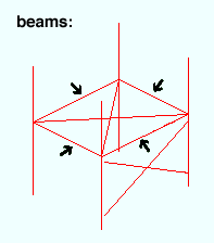
Beams are typically the most commonly used members in the model. A beam is a structural member whose primary function is to carry loads transverse to its longitudinal axis.

VIDEO Beams are added in Modeling . The procedure demonstrated in this video still applies to newer versions of SDS2 software. (Recorded in SDS2 Detailing , v7.2.)

VIDEO Roof channel beams are added to sloping beams using the point locator INCM . " Toe direction " is explained. The Beam Edit window may look different in newer versions of SDS2 programs, but these instructions still pertain. (Recorded in SDS2 Detailing , v7.2.)

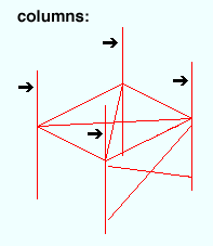
Columns are relatively long vertical or sloping member whose primary function is to carry compression loads parallel to its longitudinal axis. System connections can be designed to sloping columns as well as to columns that are perfectly vertical.

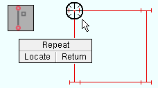
VIDEO Middle-click ( Repeat ) adds duplicates of columns.The video begins with the pressing of " OK " on a column edit window. The video which follows explains an option for Repeat that was added since the time that this video was created. (Recorded in SDS2 Detailing , v7.2.)

VIDEO

This YouTube video begins with the adding of columns with the default (off / not checked) set for User and Site Options > Modeling > " Classic colum location ." Then " Classic column location " is turned on, and the new columns are placed at the elevation of the last-added column. (Recorded in SDS2 Detailing , v2017.)

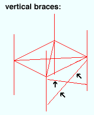
Vertical Braces are braces that slope and whose gusset plates are vertical.

VIDEO Double-angle cross bracing is created by adding three vertical braces in an elevation view . Settings discussed include " Double material " and " Long leg ." The video still pertains to recent versions of SDS2 programs. (Recorded in SDS2 Detailing , v7.2.)

  • Shown above are three vertical braces. Vertical braces can be perfectly vertical or horizontal as well as sloping. A vertical brace in any orientation can share a gusset with another vertical brace.
  • Vertical brace main material can be any section that is listed in the local shape file of your current Job. Connection design can create gusset plates on a vertical brace made of angle , channel , wide flange , S shape , welded plate wide flange , HSS rectangular , HSS round , W tee or S tee braces. You can enter double angles (back to back or in a star configuration) or double channels (back to back only) to provide additional bracing strength.

Horizontal Braces are braces that are perfectly horizontal or sloping and whose gusset plates are parallel with the flanges of the beam being framed to.
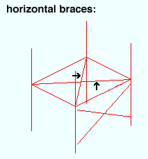
  • Horizontal braces are designed to handle torsional or twisting loads on the structure. A horizontal brace that is sloping may slope up to 30 degrees.
  • Horizontal brace main material can be any section that is listed in the local shape file . However, be aware that connection design can only generate connections for horizontal braces made of angle , W tee , S tee , HSS rectangular , HSS round , wide flange or S shape material.
  • Locate work points for non-sloping horizontal bracing while in a plan view . You can later adjust the work points' elevations using the left and right " End elevation " fields on the Horizontal Brace Edit window (both elevations must be the same).
  • To lay out a sloping horizontal brace, first go to a view that is parallel with the flanges of the beams you want to frame the brace to. Example: Use Navigate > Snap to Surface and click on the top flange of a beam to get a view in the plane of the top flange of the beam. Then use View > Relative Depth if you want to move the work plane of the view to a different position.

Joists can be rendered in Modeling using various " Panel display methods ."Joist are not auto detailed. It is assumed that a joists is ordered from a joist manufacturer and will not be shop fabricated. You can, however, generate a Joist Report which can serve as a bill of material for ordering joists.
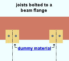
  • Settings for joists are entered on the Joist Edit window.
  • Connection design can automatically design joist seats and top chord supports for joists. These connections appear on the detail for the supporting column or beam.

Girts (legacy) and Purlins do not have any automatic connections that connection design can design for you.

  • You can get connections -- but not designed connections -- using the Girt member, which is a type of custom meber.

Miscellaneous members can be made up of any type of material that you can add to a member as a submaterial. See the Material Type Selection window for a list of these materials. Shown below is decking, one of the types of material you can add to the model as a miscellaneous member.
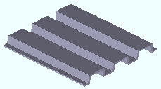
As with other member types, miscellaneous members are assigned member piecemarks . Work point layout is different for different material types. Connections are NOT automatically designed on miscellaneous members. Users need to Add Material or Add Assembly or Run Parametric to add connection materials to a miscellaneous member.

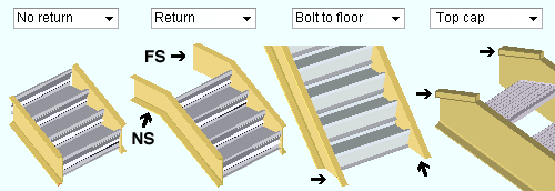
A stair can have one or two returns, no returns, or can be bolted to the floor.

  • The two work points you locate define the nosing line of the stair. Settings for stairs are entered on the Stair Edit window.

Custom members that are currently provided with SDS2 programs include Hand Rail , Embed Embed Plate , Sag Rod ( ), Anchor Rod , Caged Ladder , Roof Frame ( ) and others.

  • Since these member types are developed from parametric Python code, they are relatively easy to develop, and more types are likely to become available.
  • It is also possible for users to add new custom members or to create modified copies of the custom members that come with SDS2 programs.

page 1 | contents | overview | top


Lay out members of the same type at the same time :

  • For example, begin with columns. Lay out columns that are exactly the same as one another first, then go on to columns that are slightly different, then to other columns that are slightly different still.
  • This saves you a lot of time since once you enter a setting to a member's edit window, that same setting is applied to each subsequently added member of the same type until you change that setting (or until you exit and restart Modeling ).
  • Also, laying out like members together facilitates the use of the middle-click ( Repeat ) mouse binding.

page 1 | contents | overview | top


Locate work points :

  • Use Locators to lay out work points. By locating points in a view, you are defining the spatial geometry ( work line , end elevation, framing condition, etc.) of members within the 3D model .
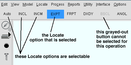
Auto INCL INCM EXPT FRPT DXDY BSCL ANGL
  • The point location target ( ) snaps to locatable points (set by the selected Locate icons) as you move the mouse pointer on screen. Left-click ( Locate ) when this symbol is where you want the member's work point.
  • The X-Y-Z display is a decoration on your toolbar that shows you the global coordinates of whatever point the point location target ( ) has snapped to. The third coordinate on this display (the Z coordinate) is the elevation of that point.
X coordinate, Y coordinate, Z coordinate

INCL ( ) (intersection of construction lines) is the most commonly used point locator. It finds points at intersections of construction lines and/or construction circles and/or grid lines. If you lay out members in a plan view using INCL (with Offset Controls set to zero offsets), the elevation of the work points you locate is the reference elevation of the plan view. For a horizontal (non-sloping) beam, this means that its top flange is at the elevation of the plan view.

INCM ( ) (intersection of a construction line and member) is an excellent choice for framing a beam to a sloping beam in a plan view. So long as Offset Controls are set to zero offsets, the work point will be at the elevation of the top flange of the sloping beam.

EXPT ( ) (exact point) finds member work points. The exact points shown below are the work points of the beam. The columns this beam frames to are displayed in stick form. The beam's material is set back from the columns' worklines because the beam frames to column flanges.
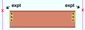
DXDY is an excellent choice for laying out sloping members such as vertical braces or sloping beams in a plan view.

DXDY to add a sloping beam
(instructions assume that you are using a 3-button mouse)
1 . Invoke Add Beam , then left-click ( Locate ) when the target ( ) snaps to where you want the beam's first point. EXPT is the Locate option used in this example.
2 . The status line prompts, "Locate second point ." Select DXDY as the Locate option, then left-click ( Locate ) anywhere in the drawing area.
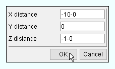
3 . In the DX/DY Offset window, enter the X, Y and Z distance from the first point to the beam's second point, then press " OK ."
4 . After you enter settings and press " OK " on the Beam Edit window, the beam appears in the view.
  • Work points for a column: You can lay out a column in a plan view with a single work point, then set the top and bottom end elevations of the column on its edit window. In an elevation view , column layout requires two points. Sloping columns can be added in an elevation view.

page 1 | contents | overview | top


Specify member settings :

  • Enter settings for both the left and right end of the member (bottom and top for columns).
  • When entering a column that has been laid out as a cross section (by locating a single work point), be sure to enter the end elevations for both the top and bottom ends of the column.
  • Sloping members may be laid out by specifying different elevations at the two ends of the member. In other words, you can change the elevations of work points on a member's edit window even after you have physically laid out those work points.
  • To quickly lay out members that are reverses of the last member you laid out, use the " Swap member ends " option.
  • Moment connections may be specified on Beam Edit windows; they cannot be applied as auto standard .

page 1 | contents | overview | top


After the member appears in the view :

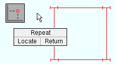
  • Middle-click ( Repeat ) to lay out members that are exactly the same as one another. The member's settings (including left and right " End elevation ") will be that of the last-added or last-edited member of the same type. The point that is snapped to when you middle-click ( Repeat ) will set the X, Y global axes location of the left end of the repeated member, but not the Z global axis location of the member's left end.
  • The point location icons that you select for placement of the first work point and second work point of a member are automatically be activated in the same order the next time you lay out a member of that same type (unless you exit and restart Modeling in the meantime).

page 1 | contents | overview | top


Also note :

  • Member Copy can be used as an alternative to Add Member for laying out the structural model.
  • Move/Stretch Members or Move/Stretch Members, Include Material can speed up member layout by letting you reposition members instead of having to delete them then add them again. You can, for instance, use either of these tools to relocate an entire line of columns and simultaneously lengthen or shorten the beams that frame to those columns.
  • Open ( Ctrl + o ) a plan view of the next highest floor. If columns you input earlier pass through this elevation, you will see cross sections of them in the view. Add members in this view as needed.
  • After you have laid out several floors, use Isometric View ( ) to create an isometric view of the entire structure. Use Save View As to give this new view a name (for instance, name it "iso").

Also see :

page 1 | contents | overview | top