The CNC Profile Machine Setup Data window
- Step-by-step instructions:
- Tabs on this window:
- General
- Torch Travel Limits
- Flange Torch Rotations
- Bevel Configuration # (6 configurations)
Step-by-step instructions :
The CNC Profile Machine Setup Data window lets you set up or change configuration information for a profile (or coping) machine. Entering correct information to this window ensures that CNC data in a download file created using the currently selected " CNC configuration " is consistent with either the way your profile machine actually behaves or includes instructions concerning the way that you want it to behave.
1 . Before opening the window:
1a : On the Computer Numerically Controlled window, confirm that the " CNC type " is ' Peddinghaus Cope ' or ' Peddinghaus Beam ' or ' Peddinghaus 3spin ' or ' Peddinghaus 9spin '.
Alternative 1 : If the " CNC type " is ' Peddinghaus Cope ', press the " Options " button on the CNC Setup window.
Alternative 2 : If the " CNC type " is ' Peddinghaus Beam ' or ' Peddinghaus 3spin ' or ' Peddinghaus 9spin ', press the " Options " button on the CNC Setup window. On the Peddinghaus Options window, make sure that the box for " Include coping data in download " is checked, then press the " Profile " button.
3 . This window, CNC Profile Machine Setup Data , opens.
3a : Confirm that correct choices are made to settings under the " General " heading.
3b : Under the Torch Travel Limits tab, enter distances (in the primary dimension " Units " or other units ) that define the precise torch-travel capabilities of your CNC machine.
3c : You may define up to six configurations (each one under a different Bevel Configuration # tab) that describe how you want your CNC machine to handle different situations. You can set up different configurations for different types of cuts (copes, bevels or both), different member types, different material types, different bevel slopes and different web cut starting points.
3d : To the Flange Torch Rotations tab, list the rotations (in degrees) that your profile machine is capable of. These rotations will be applied when a " Use nearest rotation... " option is selected for a particular Bevel Configuration # .
4 . When you are done making changes using this window, press the " OK " button at the bottom of the window to close this window. The CNC Setup window again becomes active. Press " OK " on that window to save the choices made on this window to the currently selected " CNC configuration " file in your current Job .
CNC contents | CNC setup | top
| || Bevel Configuration 1, 2, 3, 4, 5, or 6 || |
| || General || Torch Travel Limits || Flange Torch Rotations || |
Leave reference flange attached to material: ![]() or
or ![]() . If the material is cut before it is drilled or punched, you may lose the reference point on the flange.
. If the material is cut before it is drilled or punched, you may lose the reference point on the flange.
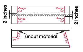
If this box is checked (
), instructions are included in the download file to cut the flange so that one inch of material is left uncut on either side of the reference flange center line, thus leaving the flange intact as a drilling/punching reference point. This material must be removed by hand at a later time.
Leave this box not checked (
) if the material is drilled first.
Download plain members (no copes or end cuts): ![]() or
or ![]() . A plain member is a member without copes or end cuts.
. A plain member is a member without copes or end cuts.
If this box is checked (
), a download file is generated even for members that do not have copes or end cuts.
If the box is not checked (
), verification prevents plain members from being downloaded. Instead of a download file , you will get the error message " No end cuts or copes detected ."
CNC contents | CNC setup | top
| || Bevel Configuration 1, 2, 3, 4, 5, or 6 || |
| || General || Torch Travel Limits || Flange Torch Rotations || |
------ Maximum ------
Torch travel distance from end of material: The maximum distance (in the primary dimension " Units " or other units ) the web torch is able to travel in along the X-axis of the material before the machine must shift the material to continue the burn.
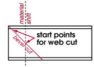
Note: This distance is measured from the end of the member, not from the beginning to the web cut.
Torch travel distance internal to material: The maximum distance (in the primary dimension " Units " or other units ) that the web torch can travel along the Y-axis of the material.

Rotated torch travel distance from end of material: The maximum distance (in the primary dimension " Units " or other units ) that the flange torch can travel along along the X-axis of the material before the machine must shift the material to continue the burn.

Rotated torch travel distance internal to material: The maximum distance (in the primary dimension " Units " or other units ) that the flange torch, when rotated, can travel along the Y-axis of the material.

------ Minimum ------
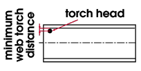
Web torch distance to inside of flange: The minimum distance (in the primary dimension " Units " or other units ) allowed between the web cut and the flange of the material.
Distance to web center line for block copes: The minimum distance (in the primary dimension " Units " or other units ) allowed from the end of a block cope to the web center line.
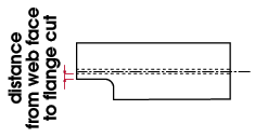
Minimum distance from web face for flange cuts: The minimum distance (in the primary dimension " Units " or other units ) that the flange cut must be from the web face.
CNC contents | CNC setup | top
| || Bevel Configuration 1, 2, 3, 4, 5, or 6 || |
| || General || Torch Travel Limits || Flange Torch Rotations || |
|
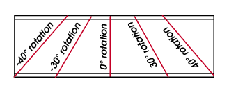
This tab lists the rotation capabilities of the flange torches on the machine that is being modeled by the currently selected " CNC configuration ." These settings apply when any of the following options are selected in an active bevel cut configuration :
|
Making entries:
- Enter the positive or negative (-) number of degrees which the flange torch on your profile machine is capable of being rotated. Notice that 0 degrees designates a vertical cut.
Why fill out this information?
Examples:
- A flange torch which is capable of only 0 degree rotation is limited to making a perpendicular cut into the flange. Flange torches on the Peddinghaus ABC1000 Profiling Machine, for instance, cannot be rotated. If the flange torches on your machine can only make perpendicular cuts into the flange, then all of the lines on this window should be set to zero (0).
- Flange torches on the Peddinghaus ABCM-1000 Profiling Machine are able to rotate 30, 40, -30 and -40 degrees. For this machine, you should enter these angles to the first four lines on this tab.
CNC contents | CNC setup | top
| || Bevel Configuration 1, 2, 3, 4, 5 or 6 || |
| || General || Torch Travel Limits || Flange Torch Rotations || |
| Each "Bevel Configuration " tab is a different bevel cut configuration that provides instructions in the download file according to the material. You can set up configurations for different types of cuts (copes, bevels or both), different member types, different material types, different bevel slopes and different web cut starting points. |
If this box is checked (
), the configuration is active, and it will be used for materials that meet the criteria under " Configuration usage " when the type of cut selected under " Flange torch, exterior to slope " or " Flange torch, interior to slope " is applied by the CNC machine to that material.
If the box is not checked (
), the configuration cannot be used.
------------------- Configuration usage ------------------------
Use for cutting copes and/or bevels: Copes or Bevels or Both .
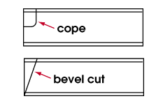
' Copes ' makes the configuration valid for copes only. Copes are non-linear cuts.
' Bevels ' makes the configuration valid for bevels only. A bevel cut is an linear cut at an angle. Bevel cuts are specified on system-generated details by bevel symbols.
' Both ' makes the configuration valid for both copes and bevels.
Use for member types: Beams or Columns or Braces or Miscellaneous or All .
Effect on the CNC download: When you " Download " a member main material, the SDS2 CNC program looks here to see if the main material being downloaded is for a member of the type selected. If it is, and this configuration applies, then this configuration will be used. ' Miscellaneous ' stands for miscellaneous members and custom members and legacy miscellaneous members .
Use for material types: Plate or Channel or Angle or Pipe or W tee or Tube steel or Wide flange or Joist or All .
Effect on the CNC download: When a download is generated for a material, the SDS2 CNC program looks to this field to see if the material being downloaded is the type that is selected. If it is, and his configuration applies, then this configuration will be used.
Use if bevel slope is: Greater than or Less than the specified "number of degrees " of slope.
To make an entry: First select either ' Greater than ' or ' Less than ', then enter the " number of degrees " of slope.
Effect on the CNC download: This field defines the number of degrees of bevel slope that a bevel must be greater or less than in order for this configuration to be used.
Use if web cut start point is: Greater than or Less than the specified " distance " (in the primary dimension " Units " or other units ) from the left end of the member.
To make an entry: First select either ' Greater than ' or ' Less than ', then enter the web cut start point ' distance ' as measured from the left end of the member.
Effect on the CNC download: This field defines the tool start point for a web cut at which you want this configuration to be used. You might want to apply this option, for instance, to very deep cuts for which there will be material shifts. You could set up one configuration for the first 12 inches into the interior of the web, and a second configuration for a material shift after that first 12 inches.
----------------- Flange torch, exterior to slope ----------------
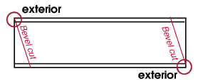
Four flange cuts and two web cuts are required to fabricate the two bevel cuts illustrated above. Red circles are drawn around the two flange cuts that are exterior to the slope. |
On bevel cuts to a wide flange section, the web will be cut by the profile machine precisely to the slope of the bevel as described in the 3D model and will stop before the torch bumps into the upper or lower flanges. Since the flange torches have limited rotations, they will, when they do their part of the bevel cut, most likely NOT be able to cut the flanges to the precise specifications described in the 3D model. The following options let you set how you want the flange torches to cut the exterior of a bevel cut to a flange. |
Cut perpendicular, locate at outside flange: ![]() or
or ![]() .
.
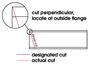
If this option is selected (
), the flange that is exterior to the designated slope of the bevel cut will be cut perpendicular beginning where the designated cut intersects with the outside face of the flange. The web torch will notch the cut to the web cut start point. In the example below, the perpendicular cut is not made since the point where the cut intersects the outside face of the flange is at the end of the member where there is no material to cut.
Cut perpendicular, locate at end of web cut: ![]() or
or ![]() .
.
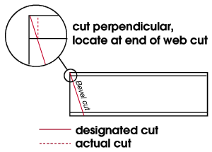
If this option is selected (
), the flange that is exterior to the designated slope of the bevel cut will be cut perpendicular so that the designated cut and the actual cut intersect at the web cut start point.
Use nearest rotation, locate at outside of flange: ![]() or
or ![]() .
.
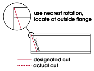
If this option is selected (
), the SDS2 CNC program determines from the entries made to the " Flange Torch Rotations " tab the nearest rotation to the designated cut, then cut through the flange at that rotation beginning where the designated cut intersects the outside face of the flange. The web torch will notch the cut to the web cut start point. Only machines with flange torches that rotate (e.g. the Peddinghaus ABCM-1000) should use this option).
Use nearest rotation, locate at end of web cut: ![]() or
or ![]() .
.
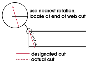
If this option is selected (
), the SDS2 CNC program references the entries made to the " Flange Torch Rotations " tab to determine the rotation that is nearest to the designated cut, then cuts through the flange at that rotation until it connects to the web cut start point. Only machines with flange torches that rotate (e.g. the Peddinghaus ABCM-1000) should use this option.
-------------------- Flange torch, interior to slope --------------------

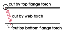
When a bevel cut is made to a wide flange section, the cut is divided into three parts: the top flange is cut by the top flange torch, the web is cut by the web cut torch, and the bottom flange is cut by the bottom flange torch. |
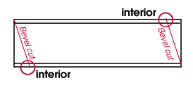
Four flange cuts and two web cuts are required to fabricate the two bevel cuts illustrated above. Red circles are drawn around the two flange cuts that are interior to the slope. |
Cut perpendicular, locate at outside of flange: ![]() or
or ![]() .
.
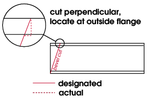
If this option is selected (
), the flange that is interior to the slope is cut perpendicular starting where the designated cut intersects the outside face of the flange. The actual cut is notched to the web cut start point, where it continues at the correct slope.
Cut perpendicular, locate at end of web cut: ![]() or
or ![]() .
.
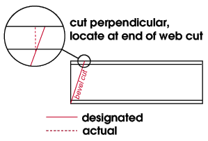
If this option is selected (
), the flange that is interior to the slope of the designated bevel cut is cut perpendicular until it meets up with the web cut start point. When the web cut start point is reached, the bevel continues at the correct slope.
Use nearest rotation, locate at outside flange: ![]() or
or ![]() .
.
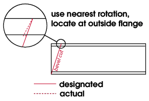
If this option is selected (
), the SDS2 CNC program looks at the entries made to the " Flange Torch Rotations " tab to determine the nearest rotation. The actual cut is made through the flange at the closest rotation to the designated slope, beginning at the point where the designated cut intersects with the outside face of the flange. The actual cut will then be notched to the web cut start point, where the bevel will continue at the correct slope.
Use nearest rotation, locate at end of web cut: ![]() or
or ![]() .
.
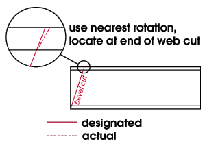
If this option is selected (
), the actual cut is made through the flange at the closest rotation to the designated slope. The SDS2 CNC program determines which rotation to use from the entries made to the Flange Torch Rotations tab. The designated slope and actual cut will intersect at the end of the web cut.
CNC contents | CNC setup | top
