Miscellaneous Members (general settings and related topics)
Miscellaneous member types (the complete list) :
Bent Plate Flat Bar Rectangular Plate Round Plate Bent Plate Layout Grating Rolled Plate Shear/Threaded Stud Clevis Grate Tread Rolled Section Square Bar Decking Plate Layout Round Bar Turnbuckle To add an above-listed type of miscellaneous member: In Modeling , press F2 > filter for "
Miscellaneous steel " > double-click the "[type]."
Note: All miscellaneous members in this list are custom members . Their plugins can be found in the
plugins/SDS2/Members/Steel/MiscellaneousCM folder.
Miscellaneous members versus legacy miscellaneous members :
Miscellaneous members are listed above . Legacy miscellaneous members are members whose member settings are stored on the [Legacy] Miscellaneous Member Edit window. Miscellaneous members provide superior functionality and ease-of-use characteristics to the legacy miscellaneous members that they can replace.
|
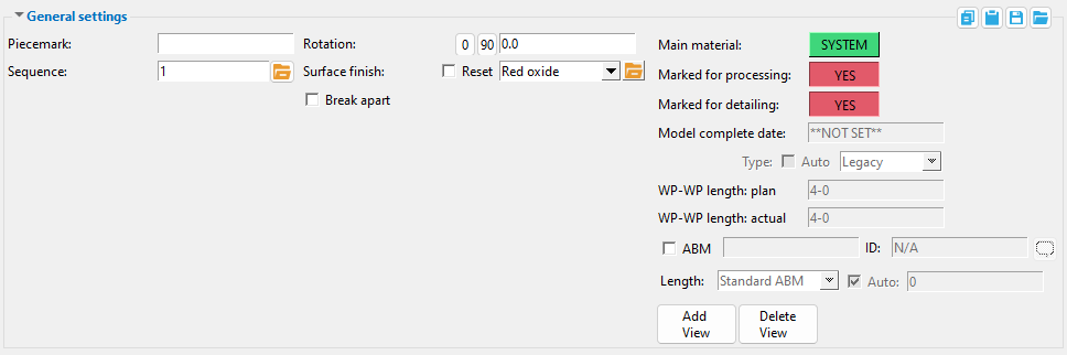
General settings common to all miscellaneous members :
Piecemark: The member piecemark of the miscellaneous member.
Typing in characters makes the piecemark a user piecemark .
To clear a user piecemark, or if you are adding a new miscellaneous member, leave this field blank. Piecemarking will assign a system piecemark when you press " OK ."
Status Display: Member status > Member piecemark (multi-select)
Status Display: General status options > Piecemark (one piecemark)
Display Options: Member piecemarks
Event logging: Piecemark
Report Writer: Member.Piecemark
Advanced Selection: m.Piecemark
Advanced Selection: m.SystemPiecemark
Parametric module: m.Piecemark
Parametric module: m.SystemPiecemark
Sequence: Any sequence name from the Sequence Names setup list can be entered. Either type the sequence, or you can press the "file cabinet" browse button ( ![]() ) and double-click any sequence name that is on the list.
) and double-click any sequence name that is on the list.
Tip: If you want to add a new sequence so that it can be selected here, you should first increase the number of " Maximum sequences " that are available.
Setup: Zone and Sequence screen
Topic: Dividing a model into sequences/zones
Tools: Sequence by Area , Set Sequence , Update Attributes
Status Display: General status options > Sequence and Zone
Status Report by XXX: Sequence and Zone
Report Writer: Member.ErectionSequence
Report Writer: Member.ErectionZone (the " Sequence " sets the zone)
Advanced Selection: m.ErectionSequence
Advanced Selection: m.ErectionZone (the " Sequence " sets the zone)
Parametric module: m.ErectionSequence
Parametric module: m.ErectionZone (the " Sequence " sets the zone)
Rotation: A positive (+) or negative (-) number of degrees . The member is rotated around its member line. For a bent plate layout or plate layout, the rotation is around the first two points that were located when the member was added. ' -90 ' degrees is the default when you first add a miscellaneous member in a plan view.
Assuming that you are looking at the profile of the member from the end opposite to its origin . . .
' 0 ' degrees positions the member 90 degrees counterclockwise from the default position (-90).
A ' positive number ' rotates the member that number of degrees counterclockwise from the zero position.
A ' negative (-) number ' rotates the member clockwise from the zero position.
' 90 ' rotates the miscellaneous member 90 degrees clockwise from the zero position.
Note: The origin of a miscellaneous member is its member coordinate system's 0, 0, 0 point. It coincides with the first point located when the member was added and sets the member's left end. Exception: a round plate.
Tip: You should use this option to rotate a miscellaneous member instead of rotating its material.
Report Writer:Member.Rotation (in radians)
Surface finish: None or Sandblasted or Red oxide or Yellow zinc or Gray oxide or Blued steel or Galvanized or Duplex Coating or Undefined 1 or Undefined 2 or Undefined 3 or Red oxide 2 or Any user added surface finish. This affects the colors of 'Solid ' members on erection views in the Drawing Editor . This also sets the color when "Output material color " is set to 'Surface finish ' for a VRML Export or a DWG/DXF Export . The "Color " ( not "Surface finish ") sets the color of this material in Modeling .
| sand blasted | red oxide | yellow zinc | user surface finish 1 |
| gray oxide | blued steel | galvanized | user surface finish 2 |
To assign a different surface finish, you can drop-down the current surface finish and select the one you want, or you can press the "file cabinet" browse button (
) and double-click any surface finish that is on the list.
Reset ![]() or
or ![]() .
.
If this box is checked (
If the box is not checked (
), all attached materials' surface finish remains at what is set inside the material edit window.
Note 1: If the material surface finish changes from what the member level has set, an information tag is shown next to the surface finish in the member edit window. This notifies the user that an attached material has been changed by a user from what was set on the member level.
Note 2:Member Piecemarks can be split apart by surface finish. All surface finishes that do not have the 'Break Marks Member' checked on can be applied to any like member with out the member splitting. If the 'Break Marks Member' is checked on then only like members with that specific surface finish can have the same piecemark.
Note 3:When exporting a KISS file using "model" as the "Data source " surface finish data on the materials are compiled into the KISS download as follows, with a few exceptions (G=galvanized, N= none or sandblasted, P= others). Those exceptions are:
If the box for "Finish" routing in KISS export setup is set to a user routing
If the user has adjusted the Abbreviation for any of the default provided surface finishes
If you are using a user added surface finish
In these cases you will get what is provided in either the User routing, or the abbreviation field. For other exports it will always provide the abbreviation in the 'surface finishes' settings page.
Tip 1: "Surface area" is reported on the General Information inside the material edit window -- and this can be used to estimate the amount of coating required and its cost.
Tip 2: Changing "Steel grade " "Color " and "Surface finish " do not cause the material to be regenerated. This means that, if you change those settings only, material fit operations such as a Fit Exact may, optionally, be preserved.
Report Writer:MemberMaterial.Material.SurfaceFinish
Setup:Surface Finish Settings
Update Attributes:Surface finish reset:
Update Attributes:Surface finish value:
Status Display:Member status > Surface Finish
Break apart: ![]() or
or ![]() . You may do this, for example, if you also want to galvanize this member. When " Automatically break apart galvanized members " is enabled in the Fabricator Options > Galvanizing Settings window, checking this option will automatically check the " Galvanized " option when you press " OK ."
. You may do this, for example, if you also want to galvanize this member. When " Automatically break apart galvanized members " is enabled in the Fabricator Options > Galvanizing Settings window, checking this option will automatically check the " Galvanized " option when you press " OK ."
If this box is checked (
If this box is not checked (
Tip: Although broken apart members are robust and adaptive to changes you make in the model, you should avoid making dramatic changes to them.
Main material: ![]() or
or ![]() or
or ![]() . You can click on this "
. You can click on this " ![]() General settings " button to switch it from ' USER ' to ' SYSTEM ' or vice-versa. To make graphical main material regenerated as system main material, click this button so that it says ' SYSTEM ' then press " OK " on the member edit window (so that Create Solids is performed).
General settings " button to switch it from ' USER ' to ' SYSTEM ' or vice-versa. To make graphical main material regenerated as system main material, click this button so that it says ' SYSTEM ' then press " OK " on the member edit window (so that Create Solids is performed).
|
|||||||||||||||||||||||||||||||||||
|
|
||||||||||||||||||||||||||||||||||
|
Altering a miscellaneous member's main material by changing the main material's " Width " or " Thickness " or its left- or right-end " |
|||||||||||||||||||||||||||||||||||
indicates the miscellaneous member's main material (for some members, its " Section size ") has been made graphical. As a result, the main material will not undergo Process and Create Solids and, as a consequence, its main material will not be regenerated per the settings on this window. For example, if this reads ' USER ' on the Rectangular Plate Edit window and a " Plate thickness " of 8 inches has been entered to the Rectangular Plate Material window, it doesn't matter what entry you make to " Plate thickness " on the miscellaneous member's Rectangular Plate Edit window -- the actual thickness in the model will be 8 inches.
indicates that the member's main material will be regenerated when, for example, you press "OK" to close the miscellaneous member edit window.
indicates mixed entries . You can set all members you are editing to ' USER ' or ' SYSTEM ' or keep them mixed.
Tip: You can change some settings on a miscellaneous member's material window without " Main material " being automatically set to ' USER '. For example, you can change the material's " Surface finish " or its " Color. "
Status Display: Detailing and processing > Graphically altered members
Report Writer: Member.Conditions.MarkedAsGraphicallyAltered
Advanced Selection: m.MarkedAsGraphicallyAltered
Parametric module: m.MarkedAsGraphicallyAltered
Marked for processing: ![]() or
or ![]() or
or ![]() . The term " Process " as it is used here means " Process and Create Solids ." Under most circumstances, this "
. The term " Process " as it is used here means " Process and Create Solids ." Under most circumstances, this " ![]() General settings " button will read " YES " only when Create Solids still needs to be performed on the member. The Process part of Process and Create Solids is almost never required because Process within member edit automatically performs the Process phases of Process and Create Solids whenever you open a member edit window.
General settings " button will read " YES " only when Create Solids still needs to be performed on the member. The Process part of Process and Create Solids is almost never required because Process within member edit automatically performs the Process phases of Process and Create Solids whenever you open a member edit window.
means this member will automatically be selected the next time you Process and Create Solids or Create Solids for Selected Members . A member is automatically marked for solids creation and potentially additional phases of processing when its settings have been revised and User and Site Options > Modeling > " Automatically process after modeling operation " is set to ' Process ' or ' Do nothing '.. To make this read " NO " when " Automatically process after modeling operation " is ' Process and create solids ', all you have to do is press the " OK " button on the member edit window. On the other hand, if that option is ' Process ' or ' Do nothing ', you will have to Process and Create Solids to make this read ' NO ' the next time you open this window. Members that are marked for solids creation can only be displayed in stick form .
means the member has undergone all phases of Process and Create Solids and has not since that time been marked for Process or Create Solids . To make this button to read " YES " without first closing this window, click this button.
Related Topics: When members are automatically marked for Process or marked for Create Solids , Reasons to mark members for processing .
Related Tools: Mark Members for Processing , Mark All Members in View for Processing
Status Display: Detailing and processing > Needs to be processed
Status Display: Detailing and processing > Needs solids created
Hide Items: Process required
Advanced Selection: m.MarkedForCreate3d
Report Writer: Member.LeftEnd.MarkedforProcess
Marked for detailing: ![]() or
or ![]() or
or ![]() . You can click this "
. You can click this " ![]() General settings " button to switch it from " YES " to " NO " or vice-versa.
General settings " button to switch it from " YES " to " NO " or vice-versa.
Hide Items: Detail required
Status Display: Detailing and processing > Needs to be detailed
Report Writer: Member.Conditions.Markedfordetail
Advanced Selection: m.MarkedForDetail
Parametric module: m.MarkedForDetail
Model complete date: **NOT SET** or a month day year (see entering dates ). A model completed date that is set here will be applied unless the miscellaneous member is marked for Process or marked for Create Solids .
' **NOT SET** ' indicates that this window is fully editable.
If a ' month day year ' is entered, the affected member is prevented from being altered during the solids creation phase of Process and Create Solids . If ' Restrictive ' is selected below (or if "
Operations If event logging for " " for " Members " is turned on (
Log " of the affected member. The "
Status Update: Model completed
Status Display: Approval and modeling > Model complete date
Status Report by XXX: Model complete
Parametric member module: mem1.DateModelCompleted
Report Writer: Member.DateModelCompleted
Advanced Selection: m.DateModelCompleted
Parametric module: m.DateModelCompleted
Hide Items: Model complete '
Type: Auto or Restrictive or Legacy . This " ![]() General settings " option applies after you have entered a " Model complete date " to a member.
General settings " option applies after you have entered a " Model complete date " to a member.
If " Auto " is checked (
If " Auto " is not checked (
' Restrictive ' "freezes" the model complete member, helping to ensure that its member piecemark and submaterial marks and solids model will not change. Process and Create Solids cannot change the member or generate connections to the restrictive-model-complete member. Materials , bolts , welds and holes cannot be added to, copied to, deleted from or changed on the member. The member cannot be erased, moved or deleted. All settings on the member's edit window become read-only ( disabled ), though the " Piecemark " field and " Status " " Properties " " Add View " and " Delete View " buttons remain operational. You can change status settings or member custom properties that do not affect piecemarking or detailing.
' Legacy ' applies only a single restriction to the affected member. During its Create Solids phases, Process and Create Solids is restricted from regenerating any materials that comprise the affected member. This restriction preserves the solids model in whatever state was in when the " Model complete date " was set.
Regardless of the choice made here: If you Copy a model-complete member, the " Model complete date " on the new member will, by default, be set per User and Site Options > Modeling > Member status items to copy/repeat and can be overridden as described here . If event logging for " Operations " for " Members " is turned on (
Update Attributes: Model complete type
Setup: Home > Project Settings > Job > Member and Drawing Restrictions > " Auto model complete type "
WP to WP length, plan: read-only . The work point-to-work point distance (in the primary dimension " Units ") spanned by the member's workline in a plan view, ignoring elevation. This " ![]() General settings " distance is calculated from the X and Y (but not Z) global coordinates of the member's work points.
General settings " distance is calculated from the X and Y (but not Z) global coordinates of the member's work points.
Note: If the member is sloped out of the plan view elevation, the distance reported here will not be the actual work point-to-work point length, but rather the distance between the ends of its member line as measured at a single elevation.
Report Writer: Member.WorkpointToWorkpointLevel
Advanced Selection: m.WorkpointToWorkpointLevel
Parametric module: m.WorkpointToWorkpointLevel
WP to WP length, actual: Read-only . The actual length of this member's workline (in the primary dimension " Units "). This " ![]() General settings " distance is calculated from the X and Y and Z global coordinates of the member's work points .
General settings " distance is calculated from the X and Y and Z global coordinates of the member's work points .
Tip: Using Move/Stretch Members or Move/Stretch Members, Include Material to lengthen or shorten a member or changing a member's " End elevation " on one end causes a different distance to be reported here.
Report Writer: Member.WorkpointToWorkpointSlope
Advanced Selection: m.WorkpointToWorkpointSlope
Parametric module: m.WorkpointToWorkpointSlope
ABM
| Special Buttons for Detailing this Miscellaneous Member | |||
|
|
|
||
| Press this button to open a window with a list of preset views that you can select. When you Detail this miscellaneous member, any preset view you select will be drawn on the detail. | Press this button to open a list of views you can delete. If this miscellaneous member has only a main view, you will get a warning instead of a list of views since you cannot delete the main view. | ||
| Tip : When the setup option " Detailed " is set to ' In position ', isolation's main view is the view shown on the detail, and the preset views are based off of that main view. If " Detailed " is set to ' Horizontal ' or ' Vertical ', the main view is always shown flat, and the preset views that are selected are based off of that flat view. |
Bottom-row buttons, miscellaneous custom members :
![]()
![]()
![]()
![]()
![]()
![]()
![]() ( form buttons ) are named " Copy " " Paste " " Save " and " Load ."
( form buttons ) are named " Copy " " Paste " " Save " and " Load ."
When form buttons are embedded in the headers for individual leaves on a miscellaneous member window, the buttons apply only to the settings that are contained in that leaf.
Click here for more information about how form buttons work.
"Properties" opens the Edit Properties window, on which you can make entries to custom properties . If, at the time it was created, your current Job was set to use a legacy flavor, the window that opens is named Custom Properties , not Edit Properties .
The Edit Properties window can also be used to read "
The " Properties " button is disabled ( grayed out ) when a new miscellaneous member is being added.
Tip: Model > Member > Properties is an alternative to this button. It opens the Edit Properties window without your first having to open a member edit window.
" Status " opens the Member Status Review window, which can give you additional information about this miscellaneous member, and which you can use to enter status information.
"OK" (or the Enter key) closes this window and saves the settings on it.


Red-colored highlighting identifies an entry that is invalid. You need to change that setting, or you will not be able to close this window using " OK ." The " Piecemark " that is shown, if it is a system piecemark, may change after you press " OK ." If there is no " Piecemark " shown, a system member piecemark will be assigned after you press " OK ."
Solids on "OK": If the appropriate choice is made to User and Site Options > Modeling > " Automatically process after modeling operation ," then the member will automatically be regenerated ( Create Solids will take place) after your press " OK ." Otherwise, you will have to manually Process and Create Solids in order for changes you made on this window to be fully updated in the 3D model.
"Cancel" (or the Esc key) closes this window without changing (or adding) the miscellaneous member you are editing (or adding).
"Reset" undoes any changes made since you first opened this window. That is to say, " Reset " populates this window with the settings that were originally entered to it when you first opened the window. The window remains open.

