
 Expanded Connection Design Calculations
The report is output as a PDF file.
- General Overview
- Step-By-Step: Home
- Step-By-Step: Member Edit
- Step-By-Step: By Location
- Tips and Tricks
- Related Tools
The Expanded Connection Design Calculations report provides the same information as the Connection Design Calculations report, but it shows you the detailed calculations and formulas written out in the report itself, instead of simply reporting the results.
For example, both the Expanded Connection Design Calculations report and the traditional Connection Design Calculations Report provide an allowable strength summary:
The Expanded Connection Design Calculations report, additionally, steps you through the calculations for determining the allowable strength:
1. On the Home > Reports page, click the Connection Design button and select Expanded Calculations.
▸ In Modeling or Drawing Editor, click the Print Expanded Calculations icon, which is pictured above. The icon can be found on the Reports page > Connections section.
Alternative: In Modeling or Drawing Editor, invoke Print Expanded Calculations using the Find Tool by searching the command name and clicking the icon, which is pictured above.
Learn more about alternative methods for launching commands.
2. A selection dialog opens. On it is a list of all members in the current job's model. Select one or more members and press OK.
Note: If you select
by Piecemark and choose a piecemark that is assigned to multiple members, a single report for the one member with the lowest member number [in brackets] will be output for that piecemark. To give you finer control, the default selection setting is
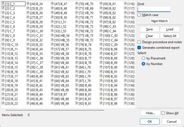
|
Save lets you save a selection.
Hide ... and Show All adjust the selection list. |
 ), individual PDF files are output for each selected member.
Alternative: Press Cancel to end this operation without generating the report.
3. The Save report as... window opens, allowing you to choose the destination for the PDF file and to change name of the file. Click the Save button to create the report, which will then automatically open in your operating system's default PDF application.
1. Edit one or more members of the same type (beam, column, vertical brace, horizontal brace, or joist).
2. In the member edit window, click the Expanded Calc button at the bottom of the window.
3. The Save report as... window opens when editing a single member at a time, allowing you to choose the destination for the PDF file and to change the name of the file. Click the Save button to create the report, which will then automatically open in your operating system's default PDF application.
Alternative: The Expanded-Calcs Report Output Folder window opens when editing multiple members at a time. This window allows you to choose the destination of a new folder and to name the folder. Click the OK button and a PDF file for each member you are editing will output to the new folder. The files do not open automatically with this option.
1. In Modeling, preselect one or more members to enable the Members contextual page and click the Print Expanded Calculations by location icon found in the Reports section.
Alternative: Invoke Print Expanded Calculations by location using the Find Tool by searching the command name and clicking the icon, which is pictured above. The status line prompts "Select members". Select one or more members, then press Enter or right-click and select OK.
2. When only one member was selected in step 1, the Save report as... window opens, allowing you to choose the destination for the PDF file and to change name of the file. Click the Save button to create the report, which will then automatically open in your operating system's default PDF application.
Alternative 1: When multiple members were selected in step 1, the Expanded-Calcs Report Output Folder window opens. This window allows you to choose the destination of a new folder and to name the folder. Click the OK button and a PDF file for each member you are editing will output to the new folder. The files do not open automatically with this option.
Alternative 2: Click Cancel to end the operation without generating a report.
- Connection Design Calculations
- Design Procedure and Notes
- Connection design method
- Graphical connections (design calculations cannot be output for)

