 Connection Design Calculations
The report is output as a PDF file.
- General Overview
- Step-By-Step: Home
- Step-By-Step: Member Edit
- Tips and Tricks
- Related Tools
Description
Design Calculations is a report about the design of particular members and their end connections. The report provides information about connection materials, member main materials, bolt types, welds, connection framing conditions, and the calculated allowable loads for each limit state that is evaluated during the course of connection design.
General information related to your job's Connection design method is provided on the optional Design Procedure and Notes. If you need the complete formulas included in your connection design report, see Expanded Connection Design Calculations Report instead.
Report Outline
This is the general outline most Design Calculations reports will follow. Additional headings and information could be shown here depending on the member type and input connection type.
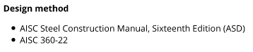
Design method: The connection design method and its references.
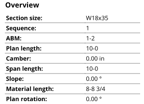
Overview: General information about the member.
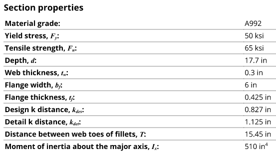
Section properties: The properties of the main member material's section size.
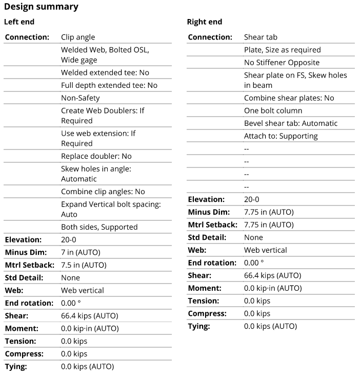
Design summary: A summary of the end connection which includes the input connection type, connection specifications, end elevation, setbacks, and loads. The information shown here will vary depending on the member type and connection type.
Member end summary
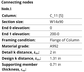
Connecting nodes: Information about the member(s) that support a particular end connection.
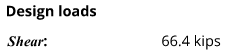
Design loads: A list of the various types of loads and their value. The value of each load was either automatically generated or manually entered by a user. Loads are sometimes referred to as reactions.
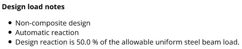
Design load notes: Additional information about the design loads, including whether they were automatically generated or manually entered by a user.
Connection summary
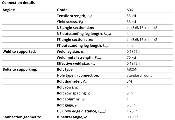
Connection details: Information about the connection material, welds, bolts, holes, and geometry. The information shown here will vary depending on the member type and connection type.
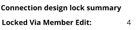
Connection design lock summary: Provides a count of the connection design locks that are locked
( in the connection.)

Warnings: Various messages can be shown to inform you about the report or about an option in the member's edit window. Sometimes the message here notifies you that the connection design requires additional review by a qualified engineer.
Examples:
"FORCED CONNECTION -- Engineering review required to evaluate strength and the application of SDS2 design calculations to the specific material and geometry" indicates that the connection is a forced connection. This report provides connection strength calculations for connections identified with this message, but does not say that the "CONNECTION IS OK" in the Notes and conclusions section of the report. The connection strength calculations should be reviewed by a qualified engineer.
"USER MAIN MATERIAL -- User modifications could interfere with connection" may be shown on a connection calculations report for beams, columns, or braces. User modifications that caused the "Main Material" to become 'USER' may include cuts to the main material that could potentially interfere with or weaken the connection. Until additional engineering review and approval has taken place, any declaration on this report that the "CONNECTION IS OK" should be viewed with skepticism.
"CONNECTION STRENGTH CALCULATIONS NOT GENERATED" typically indicates the Input connection type is set to Plain end in the member's edit window. (A similar message is received under a different heading when the connection is graphical.)
Strength summary
Limit state summary: A summary of the limit states used to evaluate the strength of a particular connection.
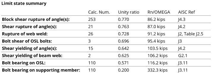
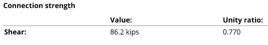
Connection strength: The overall strength value of a particular connection (also commonly referred to as the capacity of the connection). The lowest strength value shown in the Limit state summary is typically recognized as the controlling strength value for the connection. The unity ratio is also shown to represent the excess capacity of the connection. In the example below, the unity ratio of 0.770 (77%) tells you the excess capacity of the connection is 23% (19.8 kips).
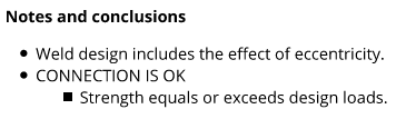
Notes and conclusions: Various notes about the connection design could be shown here along with the conclusion of the connection strength checks.
When a connection passes, the conclusion reads "CONNECTION IS OK".
When a connection fails, the conclusion reads "CONNECTION DESIGN FAILURE".
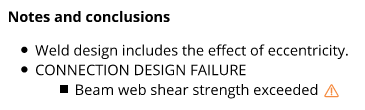
Failed connections could have failed the limit state checks during connection design or failed the clash checks during check framing situation. Along with this failure message is an end connection failure message which can help you determine the specific problem that caused the connection failure. The following links will take you to lists of such messages for beams, columns, horizontal braces, vertical braces, and joists.
1. On the Home > Reports page, click the Connection Design button and select Design (shorter) Calculations.
Alternative: In Modeling or Drawing Editor, invoke Design Calculations using the Find Tool by searching the command name and clicking the icon, which is pictured above.
Learn more about alternative methods for launching commands.
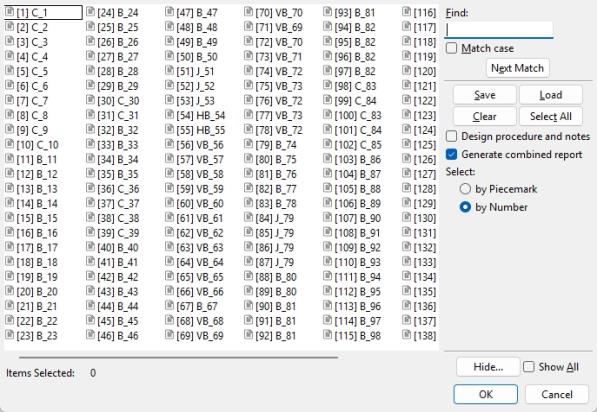
2. A selection dialog opens. On it is a list of all members in the current job's model. Select one or more members and press OK.
Note: If you select
by Piecemark and choose a piecemark that is assigned to multiple members, a single report for the one member with the lowest member number [in brackets] will be output for that piecemark. To give you finer control, the default selection setting is
|
Save lets you save a selection.
Hide ... and Show All adjust the selection list. |
 ), individual PDF files are output for each selected member.
Alternative : Press Cancel to end this operation without generating the report.
3 . The Save report as... window opens, allowing you to choose the destination for the PDF file and to change name of the file. Click the Save button to create the report, which will then automatically open in your operating system's default PDF application.
1. Edit one or more members of the same type (beam, column, vertical brace, horizontal brace, or joist).
2. In the member edit window, click the Design Calc button at the bottom of the window.
3. The Save report as... window opens when editing a single member at a time, allowing you to choose the destination for the PDF file and to change the name of the file. Click the Save button to create the report, which will then automatically open in your operating system's default PDF application.
Alternative: The Short-Calcs Report Output Folder window opens when editing multiple members at a time. This window allows you to choose the destination of a new folder and to name the folder. Click the OK button and a PDF file for each member you are editing will output to the new folder. The files do not open automatically with this option.
- Design Procedure and Notes (may be output with this report)
- Expanded Calculations (a more detailed report)
- Design Calc (button prints calcs from member edit windows -- this link is to the Column Edit window)
- Connection design method (Project Settings)
- Graphical connections (design calculations cannot be output for)

