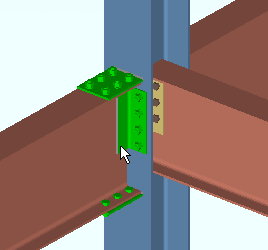
System Members and System Connections ( Modeling )
System members :
Connections that can be applied to system members :
- Designed connnections:
- Auto base/cap pate (column)
- Auto standard connections (optional for beams, columns, joists)
- Bent plate (beam, may be moment connection)
- Clip angle (beam, may be a moment connection
- Clip angle (horizontal brace)
- Clip angle (vertical brace)
- End plate (may be a moment connection)
- Flush framed shear connection (joist)
- Fully welded moment (beam)
- HBrc plate (cannot be auto standard)
- Moment Connection (beam, cannot be auto standard)
- Seated beam connection
- Seated joist connection (seat for a joist top chord)
- Shear (plate, tee, thru, may be a moment connection)
- Splice Plate Connection (beam to beam - may be a moment connection)
- Splice Plate Connection (column to column)
- User defined connection (system connection settings stored in a file)
- VBrc Plate (cannot be auto standard)
- Welded connection (cannot be auto standard)
- Designed connection that are not fully supported system connections:
- Hanger clip angles (column)
- Hanger shear connections (column)
- Other connections that can be applied to system members:
- Plain End
- User Base/Cap Plate (column, user designed, not system-designed)
- Embeds (custom members, not system-designed connections)
- Custom components (user designed, not system-designed)
- Bearing (joist to a beam's top flange)
- Bearing (beams to concrete, incorporate embed custom members)
- Stabilizer plates and angles (joist bottom chord)
- Joist seat to embed (joist to concrete)
- Stabilizer to embed (joist to concrete)
Fully supported designed system connections :
System connections are designed per the selected " Connection design method ."
Method Design Specifications ' ASD14 ' AISC Steel Construction Manual,
Fourteenth Edition' ASD13 ' AISC Steel Construction Manual,
Thirteenth Edition' ASD 9 ' AISC Manual of Steel Construction, Allowable Stress Design, 9th Edition ' LRFD 14 ' AISC Steel Construction Manual,
Fourteenth Edition' LRFD 13 ' AISC Steel Construction Manual,
Thirteenth Edition' LRFD 3 ' Manual of Steel Construction, Load and Resistance Factor Design, 3rd Edition ' CISC 10 ' CISC Handbook of Steel Construction,
Tenth Edition' CISC 9 ' CISC Handbook of Steel Construction,
Ninth Edition' CISC 8 ' CISC Handbook of Steel Construction,
Eighth EditionSystem connections are designed based on the applied loads.
Beam Loads --------------------------------------------------------------------
--
Shear load Tension load Story shear Compression load Moment load
Column Loads ------------------------------------------------------------------
--
Load Splice uplift Moment Horizontal shear
Horizontal Brace Loads -----------------------------------------------------
--
Tension load Compression load
Vertical Brace Loads ---------------------------------------------------------
--
Tension load Compression load
Joist Loads -------------------------------------------------------------------------
--
Load Designed system connections can be graphical :
|
|
|
|
|
|
Designed system connections can be forced :
|
|
|
|
|
|
Designed system connections can be edited on the Connection Component Edit window:

|
With the ' Connection Components ' filter or ' Default ' or ' All ' filter selected, double-click a system connection material to open the Connection Component Edit window for that connection. |
A failed connection is a designed system connection that failed the limit-state strength capacity testing that takes place during connection design and, as a result, produced a connection failure message such as the following:
Beam web shear capacity failed
Design calculations are available for designed system connections.
Also see :
- Macro/examples (folder where parametrics can be found)
- Connection guide (documentation on system connections)
- Custom members (another way to get connections)
- Custom components (another way to get connections) a
- Run Parametric (another way to get connections)


