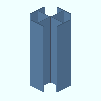
Cruciform
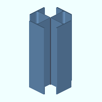
|
Cruciform wf-wt material is composed of a wide flange section and wt sections. Like other cruciform shapes, it is defined in the local shape file . In the Auto Standard Connections setup window, cruciform is referred to as cruciform column -- for example, " WFlg Beam to Crux Col perp ." The material window for wf-wt cruciform material is the Rolled Section Material window.
|
|
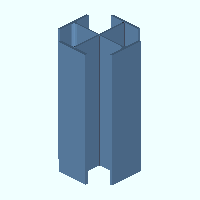
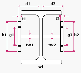
Cruciform wf-pl material is composed of a wide flange section and rectangular plates. The material window for the wide flange is the Rolled Section Material window. The material window for the plate material is the Rectangular Plate Material window.
|
|
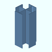
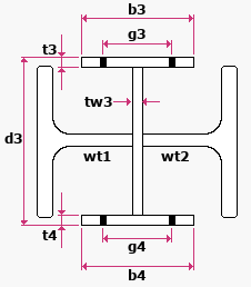
Cruciform pl-wt material is composed of W tee sections and rectangular plates. The material window for the plate material is the Rectangular Plate Material window. The material window for the W tee material is the Rolled Section Material window.
|
On this page :
Also see :
page 1 | contents | material types
Shape file specifications for cruciform wf-wt :
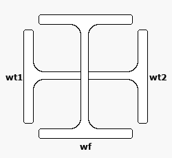
|
wf = wide flange section size
wt1 = NS tee section size
wt2 = FS tee section size
|
- Weld specifications: " NS tee weld type " and " NS tee weld size " are for welding the web of the near side W tee section to the web of the wide flange section on its near side. " FS tee weld type " and " FS tee weld size " are for welding the web of the far side W tee section to the web of the wide flange section on its far side. Shape file weld specifications set the weld symbols for shop welds shown in the 3D model and for shop weld symbols on member details.
- Other specifications: " Structural Properties " are material properties that you can edit.
- To change shape file specifications: Edit the material in Shapes Properties .
- To add a welded plate wide flange to a shape file: Use Copy Shapes in Utility Functions to copy the material from another shape file. Or you can manually add the material in Shapes Properties .
page 1 | contents | material types | top
Shape file specifications for cruciform wf-pl :
|
wf = wide flange section size
d1 = NS tee depth
tw1 = NS tee web thickness
b1 = NS tee flange width
t1 = NS tee flange thickness
g1 = NS tee flange gage
d1 = NS tee depth
tw2 = FS tee web thickness
b2 = FS tee flange width
t2 = FS tee flange thickness
g2 = FS tee flange gage
|
- Weld specifications:
- " NS tee weld type " and " NS tee weld size " are for welding the web of the near side welded plate W tee section to the web of the wide flange section on its near side.
- " FS tee weld type " and " FS tee weld size " are for welding the web of the far side welded plate W tee section to the web of the wide flange section on its far side.
- " NS tee flange weld type " and " NS tee flange weld size " are for welding the web of the near side flange to the near side web.
- " FS tee flange weld type " and " FS tee flange weld size " are for welding the web of the far side flange to the far side web.
- Shape file weld specifications set the weld symbols for shop welds shown in the 3D model and for shop weld symbols on member details.
- Other specifications: " Structural Properties " are material properties that you can edit.
- To change shape file specifications: Edit the material in Shapes Properties .
- To add a welded plate wide flange to a shape file: Use Copy Shapes in Utility Functions to copy the material from another shape file. Or you can manually add the material in Shapes Properties .
page 1 | contents | material types | top
Shape file specifications for cruciform pl-wt :
|
b3 = top flange width
t3 = top flange thickness
g3 = top flange gage
b4 = bottom flange width
t4 = bottom flange thickness
d3 = depth
tw3 = web thickness
wt1 = ns tee section size
wt2 = fs tee section size
|
- Weld specifications:
- " Top flange weld type " and " Top flange weld size " are for welding the top flange to the web of the welded plate wide flange section.
- " Bottom flange weld type " and " Bottom flange weld size " are for welding the bottom flange to the web of the welded plate wide flange section.
- " NS tee weld type " and " NS tee weld size " are for welding the web of the near side W tee section to the web of the wide flange section on its near side.
- " FS tee weld type " and " FS tee weld size " are for welding the web of the far side W tee section to the web of the wide flange section on its far side.
- Shape file weld specifications set the weld symbols for shop welds shown in the 3D model and for shop weld symbols on member details.
- Other specifications: " Structural Properties " are material properties that you can edit.
- To change shape file specifications: Edit the material in Shapes Properties .
- To add a welded plate wide flange to a shape file: Use Copy Shapes in Utility Functions to copy the material from another shape file. Or you can manually add the material in Shapes Properties .
page 1 | contents | material types | top
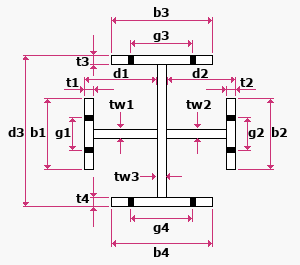
Shape file specifications for cruciform pl :
|
|
b3 = top flange width
t3 = top flange thickness
g3 = top flange gage
b4 = bottom flange width
t4 = bottom flange thickness
g4 = bottom flange gage
d3 = depth
tw3 = web thickness
|
d1 = NS tee depth
tw1 = NS tee web thickness
b1 = NS tee flange width
t1 = NS tee flange thickness
g1 = NS tee flange gage
d2 = FS tee depth
tw2 = FS tee web thickness
b2 = FS tee flange width
t2 = FS tee flange thickness
g2 = FS tee flange gage
|
- Weld specifications:
- " Top flange weld type " and " Top flange weld size " are for welding the top flange to the web of the welded plate wide flange.
- " Bottom flange weld type " and " Bottom flange weld size " are for welding the bottom flange to the web of the wide flange.
- " NS tee flange weld type " and " NS tee flange weld size " are for welding the web of the near side flange to the near side web.
- " FS tee flange weld type " and " FS tee flange weld size " are for welding the web of the far side flange to the far side web.
- Shape file weld specifications set the weld symbols for shop welds shown in the 3D model and for shop weld symbols on member details.
- Other specifications: " Structural Properties " are material properties that you can edit.
- To change shape file specifications: Edit the material in Shapes Properties .
- To add a welded plate wide flange to a shape file: Use Copy Shapes in Utility Functions to copy the material from another shape file. Or you can manually add the material in Shapes Properties .
page 1 | contents | material types | top
Adding cruciform sections to the model :
- Cruciform sections can be added to the model as the main material of a column by entering a cruciform " Section size " on a Column Edit window. Connection design can automatically create connections for cruciform columns .
- A cruciform sections can also be the " Section size " that is entered for other member types. However, connection design is not supported for cruciform members other than columns.
page 1 | contents | material types | top
Modifying cruciform sections :
- Methods for editing cruciform material depend on how the material was added. The following examples of edit methods assume that you are in Modeling with members displayed in a solids form and that you are using the ' Default ' selection filter:
- For submaterial, you can double-click the material to open -- depending on the composition of the cruciform material -- either the Rolled Section Material window (for W tee and wide flange section material), or the Rectangular Plate Material window.
- Cruciform sections can also be modified using Exact Fit , Mitre , Cope , Fuse Material , Cut on Plane , Cut Layout and Frame .
- You can change the spatial orientation of a material within the global coordinate system using Move/Stretch Members or Move/Stretch Members, Include Material . Also, you can change the spatial orientation of the material that composes the cruciform section using Move Material or Rotate Material or by changing the material's " Reference location X ," " Reference location Y " or " Reference elevation " on the General Information window.
page 1 | contents | material types | top
Steel grades :
- When you specify a cruciform " Section size " for a column, the " Steel grade " for that column is disabled ( grayed out ) since a cruciform section is a composite section composed of multiple materials which may or may not have different steel grades. Steel grades that will be applied to a selected section size come from Home > Project Settings > Job > Material Grades > Cruciform Grades .
- On the Cruciform Grades window, you can specify specific grades for the plates and/or W tees and/or wide flange materials that make up a cruciform section size.
page 1 | contents | material types | top


