The Weld Input window ( Drawing Editor )
- To open this window:
- Welds Symbol Add
- Weld Combo
- Weld Edit or double-click a weld symbol
- Edit Weld Symbol (multiple)
Also see :
|
- Weld symbol character height ( Fabricator > Detailing > Drawing Presentation > " Sizes " tab > )
- Add/Edit Weld(s) ( Modeling counterpart to this window)
- Show weld length on weld symbols ( Job > Weld Design Settings > set default for auto detailing)
- Field welds ( Erection View Detailing with weld symbols) (
 )
)
- Symbols font ( Fabricator > Detailing > Drawing Presentation > " Fonts " tab -- affects auto detailing)
- Grayed out fields (indicate mixed entries or that the field is disabled)
- Multi Items Edit (related window)
![]() " Copy " " Paste " " Save " " Load " buttons :
" Copy " " Paste " " Save " " Load " buttons :
| You can " Save " and " Load " settings from this window to and from incidences of this window in the Drawing Editor and also to and from incidences of the Add Weld(s) or Edit Weld(s ) windows in Modeling . |
- You'll find buttons like these at the top of this window and embedded in the border of individual sections on this window. At the top of this window, the buttons apply to all user-editable settings. Embedded in the border of the top of a section, the buttons apply to only those user-editable settings that are in that section. Click here for more information.
- You can " Copy " (
 ) the settings on this window, then change the " Weld__of " number you are editing using the VCR buttons, then " Paste " (
  ) those settings to the newly selected weld symbol.
- " Save " (
 ) saves a file to a global folder (
  ) that is used by your current version of SDS2. Give the file a name that will help users in other Jobs on your network identify its purpose. " Load " (
  ) changes settings for that section to the settings that are stored in the file that you select.
folder it saves to settings it saves top of this window form/weld-sym all on this window tail text weld-sym-tail tail text Arrow or Other side form/weld-sym-side all in that section
------ General settings ------
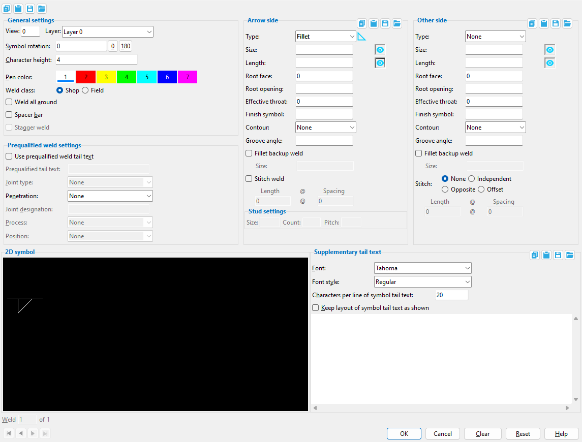
Symbol rotation: A positive or negative number of degrees from 180 to -180 that sets the rotation of the symbol with respect to horizontal.
|
An entry of ' 180 ' degrees does not flip the symbol from top to bottom (other side to arrow side). |
' 0 ' (zero) degrees results in the symbol being horizontal (not rotated).
A ' positive number ' of degrees specifies counterclockwise rotation.
A ' negative (-) number ' of degrees specifies clockwise rotation.
Note: Objects > Weld Symbols > Weld Combo automatically sets a weld's " Symbol rotation " to' 0 ' when the weld symbol attaches to a pointer that points to the left. It sets the rotation to ' 180 ' when the pointer points to the right.
Dragging a weld symbol to the opposite side of its attached pointer flips the symbol rotation 180 degrees.
Character height: The height ( in millimeters ) of lettering that is to appear on the weld symbol (e.g. weld size, tail text, etc.). This is the actual height of the lettering as it will appear on printed details that have not been rescaled.
Setup: The default character height for automatically detailed weld symbols is the " Weld symbols character height " on the Drawing Presentation window. For weld symbols added using Weld Symbol Add or Weld Edit , the default is the last-added or last-edited weld symbol -- see " OK ."
Pen color: 1 or 2 or 3 or 4 or 5 or 6 or 7 . No button is pressed if you are editing multiple weld symbols that have different pen numbers. The " Weld pen color " in Drawing Presentation sets the color that is applied during auto detailing of members.
|
|
| The selected button sets the printing pen number (and on-screen display color) of the weld symbol. Line Weights sets the thickness of each " Pen color ." |
For a TrueType font, the " Pen color " affects the display color of the text while you are in the Drawing Editor , but does not affect the plotted appearance of the " Font " so long as all pens in Line Weights are set to print in black. By default, all pens in Line Weights are set to print in black.
For the ' SDS2 ' Font, the pen color sets the stroke weight (thickness) of text characters. Line Weights assigns a particular thickness to each " Pen color ."
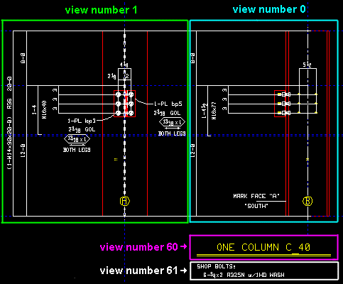
Attached to view: A number designating the view that this weld symbol is attached to. This applies mainly to member details , since member details are likely to show more views than submaterial details , the only other type of drawing on which you might find multiple views. For instance, a column detail may have a view of face A, face B and face C. It may also have various section views (Section A-A, Section B-B, Section C-C). All graphical objects that are in a particular view are assigned the same number.
Assigning the correct number to an object (line, weld symbol, label, etc.), prevents Shorten and Unshorten problems on submaterial details and member details . Automatically detailed member details and submaterial details are the two Drawing Editor drawing types that can have multiple views.
To show a view's number, you can add the X-Y-Z Display to your toolbar. An alternative decoration you can add to display view numbers is the X-Y Dual Show/True Display .
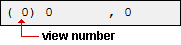
In the Drawing Editor , the X-Y-Z Display shows the view number that the point location target (
) is over.
Troubleshooting: If you Unshorten a drawing then Shorten , only to find that objects are repositioned in a way that seems wrong, the problem might be that the objects are attached to a view that is not the view that they should be attached to. A good troubleshooting method is to select all of the objects that you believe should be attached to the same view, then right-click ( Menu ) and choose " Edit " on the menu . This will open the Multi-Items Edit window. Look at the " Attached to view " field on that window. If that field is gray (shows no view number), then that field has a mixed entry , indicating that objects in your selection have have two or more different view numbers. Entering the desired view number to the " Attached to view " multi-edit field assigns all objects in your selection that one view number.
View number assignment is fairly random. While view numbers assigned during auto detailing are generally the same as the numbers assigned to views in member isolation (or material isolation's edit views mode ), there are cases where that general one-to-one correspondence will not hold. Also, while the main view of a member detail is almost always view 0, the other views are assigned numbers as they are added, and since the order in which views are added is arbitrary, there is little correspondence between a view's number and its type.
How can objects be assigned wrong view numbers? When a user adds an object to a drawing on which there are multiple views (a member detail or a submaterial detail), it is the responsibility of that user to ensure that the object is attached to the correct view. That sounds like an easy thing to do, but it isn't always so simple. Take, for example, a pointer . When a user adds a pointer using Objects > Pointers > Add , the user does not see the Pointer Edit window and therefore does not see the " Attached to view " entry field. Pointers can also be added using Paste , Paste at Original Location , Paste Repeatedly , Paste Special , Paste to Several , Add Standard Detail , Add Standard Detail to Several , Add Weld Combo , Hole Sym Combo , Label Combo , etc. Each of these tools is a different way for users to add a pointer to a wrong view.
Layer: The drawing layer that the weld symbol you are adding or editing will be drawn on after you press " OK " to close this window. If that layer happens to be hidden (not marked " Show "), the weld symbol will disappear after the first update.
![]()
Defaults: For an Weld Add operation, the default selection (
) is the layer selected on the Layer Panel when you began this operation. For an Edit Weld Symbol operation, the default selection is the layer that the graphic object is currently on.
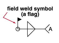
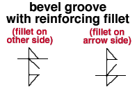
Shop designates a shop weld that joins parts as submaterials of the same shipping member. The supplementary symbol for a field welding (a flag) will not be drawn as part of the weld symbol.
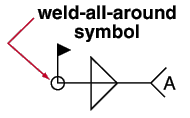
If this box is checked (
), the supplementary symbol for weld all around (a circle) will be drawn as part of the weld symbol.
If the box is not checked (
), the supplementary symbol for weld all around will not be drawn as part of the weld symbol.
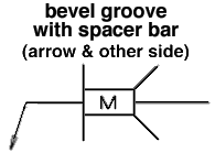
Spacer bar: ![]() or
or ![]() . A space bar can be applied when ' V groove ' or ' Bevel groove ' is selected as the " Weld type ."
. A space bar can be applied when ' V groove ' or ' Bevel groove ' is selected as the " Weld type ."
If this box is checked (
If the box is not checked (
If this box is checked (
If the box is not checked (
------ Prequalified weld settings ------
| These settings let you enter " Prequalified tail text " by selecting a " Joint type " and/or " Penetration " and/or " Weld type " and/or " Joint designation " and/or " Process " and/or " Position ." |
Use prequalified weld tail text: ![]() or
or ![]() .
.
If this box is checked (
If the box is not checked (
Prequalified tail text: You can type in the text yourself, or select a " Joint type " and/or " Penetration " and/or " Weld type " and/or " Joint designation " and/or " Process " and/or " Position ." See Table 8-2, AISC Thirteenth Edition , p. 8-34.
| Order of prequalified tail text:
joint type - penetration weld type joint dsg - process - position --------------------------------------------------------------------- Note: For a ' V groove ' (2 single; 3 double) ' Bevel groove ' (4 single; 5 double) ' U groove ' (6 single; 7 double) and ' J groove ' (8 single; 9 double), the number entered to the weld type position is different when the weld is single (arrow side only) or double (both arrow side and other side). |
Making entries: If you manually type ' BTC ' as the " Prequalified tail text ," then ' BTC ' is selected as the " Joint type ." If you type ' - L ', then ' L ' is selected as the " Penetration ." If you manually type ' - - 1 ', then ' Square groove ' (arrow side) is selected as the " Weld type ." If you type ' F ', then ' F ' is selected as the " Process ."
Joint type: None or B or C or T or BC or TC or BTC . The selection made here is automatically entered to the appropriate position in the " Prequalified tail text " (above) and on the weld symbol. See Table 8-2, AISC Thirteenth Edition , p. 8-34.
| Tail Text | Joint Type |
| B | butt joint |
| C | corner joint |
| T | T-joint |
| BC | butt or corner joint |
| TC | T or corner joint |
| BTC | butt, T- or corner joint |
Penetration: None or L or U or P . The selection made here is automatically entered to the appropriate position in the " Prequalified tail text " (above) and on the weld symbol. See Table 8-2, AISC Thirteenth Edition , p. 8-34.
| Tail Text | Penetration |
| L | limited thickness, full penetration |
| U | unlimited thickness, full penetration |
| P | partial-penetration |
Joint designation: The entry you make here ( 1 character ) is automatically entered to the appropriate position in the " Prequalified tail text " (above) and on the weld symbol. Table 8-2 on page 8-34 of the AISC Thirteenth Edition states, "The lower case letters (e.g. a, b, c, d, etc.) are used to differentiate between joints that would otherwise have the same joint designation."
Process: None or S or G or F . The selection made here is automatically entered to the appropriate position in the " Prequalified tail text " (above) and on the weld symbol. See Table 8-2, AISC Thirteenth Edition , p. 8-34.
| Tail Text | Process |
| S | submerged arc welding (SAW) |
| G | gas metal arc welding (GMAW) |
| F | flux cored arc welding (FCAW) |
Position: None or F or H or V or OH . The selection made here is automatically entered to the appropriate position in the " Prequalified tail text " (above) and on the weld symbol. See Table 8-2, AISC Thirteenth Edition , p. 8-34.
| Tail Text | Position |
| F | flat |
| H | horizontal |
| V | vertical |
| OH | overhead |
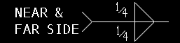
------ Arrow side (bottom) ------ | ------ Other side (top) ------
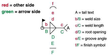
| Entries to " Arrow Side " draw the specification (symbol) below the weld symbol's reference line. Entries to " Other Side " draw the specification above the reference line. " Arrow side " refers to the side of the joint to which the arrow points. |
![]() You can " Copy " " Paste " " Save " and " Load " weld side values found on this window to and from incidences of this window in the Drawing Editor and incidences of the Add Weld(s) or Edit Weld(s ) windows in Modeling . Within this window, you can cope and paste values from the " Arrow side " to the " Other side " or vice-versa.
You can " Copy " " Paste " " Save " and " Load " weld side values found on this window to and from incidences of this window in the Drawing Editor and incidences of the Add Weld(s) or Edit Weld(s ) windows in Modeling . Within this window, you can cope and paste values from the " Arrow side " to the " Other side " or vice-versa.
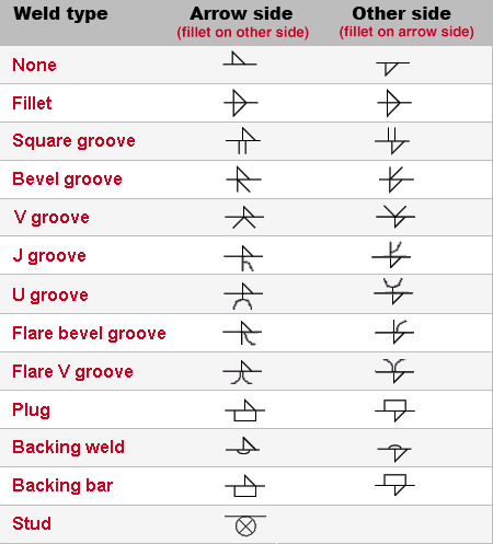
Type: None or Fillet or Square groove or Bevel groove or V groove or J groove or U groove or Flare bevel groove or Flare V groove or Plug or Backing weld or Backing bar or Stud .
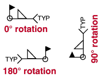
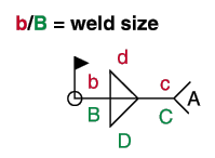
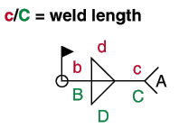
Size: A distance ( any units ) that designates the depth of preparation, size or strength for the weld. This distance will appear on the weld symbol (reference b/B in the illustration below). You can type in the weld size or select a weld size from the combo box menu. The eye button's state ( ![]() or
or ![]() or
or ![]() ) can be changed.
) can be changed.
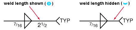
| YouTube video: Weld size and length visibility .
|
The eye button may be set to
( show ) or
( don't show ) or
( mixed ). It affects how weld symbols are drawn on member details.
Also see: The eye button (
Length: A distance ( any units , up to 15 characters) that designates the length of the weld. The weld length entered here -- even an entry of ' 0 ' -- appears in the appropriate location on the weld symbol (reference c/C in the illustration bellow) when the eye button is set to show your entry.
| YouTube video: Weld size and length visibility .
|
The eye button may be set to
Also see: The eye button (
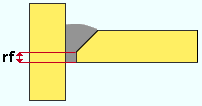
Root face: A distance (in the primary dimension " Units " or other units ) that defines the root face for groove welds. The root face is the portion of a prepared edge that is not beveled or grooved.
|
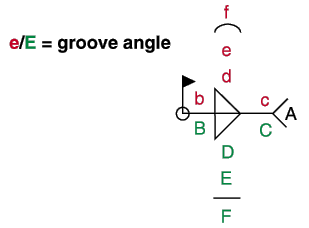
Root opening: A distance (in the primary dimension " Units " or other units ) that designates the root opening, depth of fillet for plug and slot welds (reference d/D in the illustration below).
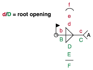
Groove angle: The number of degrees of the groove angle or included angle of countersink for plug welds (reference e/E in the illustration below).
Contour: None or Flush or Convex or Concave or Smooth toes .
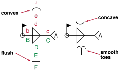
' None ' results in no contour symbol being included as part of the weld symbol.
' Flush ' adds a flat line as the contour symbol to the weld symbol.
' Concave ' adds a concave line as the contour symbol to the weld symbol.
' Convex ' adds a convex line as the contour symbol to the weld symbol.
' Smooth toes ' adds a contour symbol that looks like two back-to-back J's. It serves as an instruction to the welder to perform weld toe grinding.
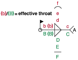
Effective throat: A distance (in the primary dimension " Units " or other units ). In a fillet weld, this is the distance from the root to the face of the weld. This distance is measured in the plane where the weld is most likely to fail. An " Effective throat " distance may be applied to weld symbols for bevel and groove welds, not just fillet welds.
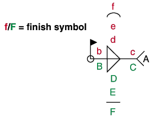
Finish symbol: A single letter to appear on the weld symbol to designate the finish (reference f/F in the illustration below).
Fillet backup weld: ![]() or
or ![]() . A backup weld can be applied when ' Square groove ' or ' Bevel groove ' or ' J groove ' or ' Flare J groove ' is selected as the " Weld type ."
. A backup weld can be applied when ' Square groove ' or ' Bevel groove ' or ' J groove ' or ' Flare J groove ' is selected as the " Weld type ."
If this box is checked (
If the box is not checked (
Size: The size of the Fillet backup weld. The size field activates when the " Fillet backup weld " box is checked ( ![]() ) . The size must be manually typed or pasted into the field. The size is shown on the Fillet backup weld symbol. Leave the field blank if you do not want the size annotation shown on the fillet backup weld symbol.
) . The size must be manually typed or pasted into the field. The size is shown on the Fillet backup weld symbol. Leave the field blank if you do not want the size annotation shown on the fillet backup weld symbol.
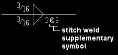
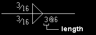
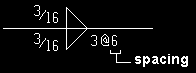
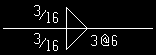
------ Arrow side stitch welds ------
Stitch weld: ![]() or
or ![]() . This sets whether or not the arrow side's stitch weld supplementary symbol appears as part of the weld symbol.
. This sets whether or not the arrow side's stitch weld supplementary symbol appears as part of the weld symbol.
|
If this box is checked (
If the box is not checked (
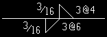
Length: A distance (in the primary dimension " Units " or other units ). This is the length that appears on the arrow side's stitch weld supplementary symbol before the "@" symbol.
|
Spacing: The spacing distance (in the primary dimension " Units " or other units ) that appears on the arrow side's stitch weld supplementary symbol after the "@" symbol.
|
------ Stud settings ------
(apply when ' Stud ' is selected as the arrow side " Weld type ")
Size: The stud diameter . This applies when ' Stud ' is selected as the arrow side " Weld type ." You can enter any numerical or alphabetical stud diameter value in any units (up to 15 characters). Leaving " Size " blank results in no value being shown on the symbol.
| YouTube video: Stud weld settings .
|
|
Size = ' 1/2 ' |
Count: The number of studs . This applies when ' Stud ' is selected as the arrow side " Weld type ." You can enter any numerical or alphabetical value in any units (up to 15 characters). Leaving " Count " blank results in no value being shown on the symbol.
|
|
Count = ' 6 ' |
Pitch: The stud spacing . This is also the midpoint-to-midpoint spacing between stud welds. It applies when ' Stud ' is selected as the arrow side " Weld type ." You can enter any numerical or alphabetical value in any units (up to 15 characters). Leaving " Pitch " blank results in no value being shown on the symbol.
|
|
Pitch = ' 7 ' |
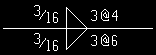
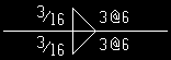
------ Other side stitch welds ------
Stitch: ![]() None or
None or ![]() Independent or
Independent or ![]() Opposite or
Opposite or ![]() Offset .
Offset .
' None '
|
' Independent '
|
' Opposite'
|
' Offset '
|
'
'
'
'
Length: Same as " Length " for the arrow side , except that this applies to the other side.
Spacing: Same as " Spacing " for the arrow side , except that this applies to the other side.
Supplementary tail text: Blank or a string of characters . the Enter key creates a line break when the cursor is in the text-entry area, resulting in multi-line tail text such as that shown in the example below. Special characters can be added as " Supplementary tail text " using Latin 1 characters 0160 to 0255 -- hold down the Alt key and type in the number using your numerical keypad, or copy and paste from the Character Map that can be launched from your operating system's Accessories menu.
| Tail text entered here : | |
|
|
| Tail text on weld symbol : | |
|
If this field is left ' blank ', a tail is not drawn on the weld symbol.
If a ' character string ' is entered, a tail with that character string as the tail text is drawn on the weld symbol.
You can " Copy " " Paste " " Save " and " Load " weld tail text found on this window to and from incidences of this window in the Drawing Editor and incidences of the Add Weld(s) or Edit Weld(s ) windows in Modeling .
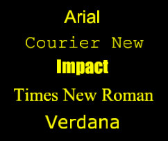
Font: Any font that is listed can be selected for the " Supplementary tail text " and " Weld size " and " Weld length " on the weld symbol.
|
Shown here are some of the TrueType fonts that you may have available on your computer. With these fonts, what you see in the Drawing Editor is what you will get on the printed drawing. For the ' SDS2 ' font, the printed thickness of the font is set by the " Pen color ." |
Be sure to also choose the " Font style " that you want. The " Weld symbols character height " (in Drawing Presentation setup) sets the font size. If you select the ' SDS2 ' font, be aware that the " Pen color " affects the thickness of the font when it is plotted.
Font style: The style (' Bold ' or ' Bold Italic ' or ' Italic ' or ' Regular ') of the selected weld symbol " Font ." Different fonts may have different styles available to them.
Available font styles are listed alphabetically in the font style list box , and the first style that is listed for a particular font is the style that is selected by default. You may, instead of using the default, prefer to choose ' Regular ', which is generally the most popular style for a particular font. ' Regular ' is the only choice that is available for the ' SDS2 ' font. To adjust the stroke thickness of the ' SDS2 ' font, you can change the " Pen color ."
Also see: Home > Project Settings > Fabricator > Drawing Presentation > the " Fonts " tab > " Symbols font " and " Symbols font style " determine the font and font style that are applied automatically to weld symbols that are generated during automatic detailing .
Characters per line of symbol tail text: The maximum length for a line of supplementary tail text measured by the number of characters. The text will wrap to the next line when this length is exceeded. The default value is 20. This value must be greater than or equal to 10 and less than or equal to 50. A preview of the tail text is drawn on the " 2D symbol ".
Also see: Home > Project Settings > Fabricator > Detailing > Detailing Symbol Settings > " Maximum number of characters per line of weld tail text "
Keep layout of symbol tail text as shown: ![]() or
or ![]() .
.
If this box is checked (
If the box is not checked (
For when you edit one weld symbol and multiple weld symbols are in the drawing :
Weld _ of __ ( not applicable to Add or multi-edit ): The number of the one weld symbol you are editing and the total count of all weld symbols in your current drawing. You can use the VCR buttons to select a different weld symbol and edit that weld symbol's settings while still on this window. When a weld symbol on a shown layer is selected, it is displayed in green. The selected weld symbol must be on a shown layer for it to be shown.
|
|
| VCR buttons (first-previous-next-last) for selecting a weld symbol to edit. |
Note: If you change one weld symbol, then select a different weld symbol number, the first weld symbol remains changed even if you press " Cancel " on this window.
To close this window :
"OK" (or the Enter key) closes this window and completes the Weld Symbol Add or Weld Edit or Edit Weld (multiple) or Weld Combo operation.
Defaults: When you press " OK ," the settings on this window -- except mixed entries -- become the default settings for the next weld symbol you Add or Combo during this session of the Drawing Editor . Even if all you do is double-click a weld symbol and press " OK " without making any changes on this window, this window's settings become the defaults for the next-added weld symbol.
"Cancel" (or the Esc key or the ![]() button) closes this window without saving changes you have made." Cancel " only cancels the changes made to the weld symbol whose number is currently selected as the " Weld _ of __ ."
button) closes this window without saving changes you have made." Cancel " only cancels the changes made to the weld symbol whose number is currently selected as the " Weld _ of __ ."
Defaults: The settings on this window do not become the defaults for new weld symbols if you press " Cancel " to close this window (unless you used " Weld _ of __ ").
Tip 1: If you used " Weld _ of __ " to edit more than one weld symbol, then Undo (after you have closed this window) does undo all changes made using this window.
Tip 2: If you double-click a weld symbol just to review it and don't want to set the defaults for to-be-added weld symbols, the best way to close this window is to press " Cancel. "
"Clear" resets all fields on this window to null values. For example, it sets " Weld type " to ' None ', blanks out the " Supplementary tail text " and sets " Symbol rotation " to ' 0 '.
Tip: If you press " Clear " and don't like the results, " Reset " brings back the original settings that were on this window when it was first opened.
"Reset" brings back the original settings that were on this window when it was first opened. If you changed the number selected in the " Weld _ of __ " widget, then it brings back the original settings for that number. The window remains open.

