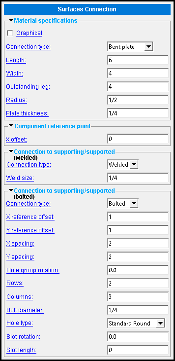
The Surfaces Connection edit window ( Modeling )
| Warning! Most changes that you make to surfaces connection materials ( bent plate or rectangular plate ) outside of this window will cause this member to be made " |
Click here for instructions on adding a surfaces connection.
Settings that control the connection are a " Component " that is stored in a [ Surfaces connection ] section on the edit window of the member it is added to.
One way to edit the Surfaces connection component is to open the edit window of the member to which it is attached. Another way is to double-click the surfaces connection with the " Selection filter " set to ' Default ' or ' All ' or ' Custom Components '.
Note: Because Surfaces Connection relies on specific surfaces, it is not copied when the member it belongs to is copied.
- Add Surfaces Connection (link is to another page)
Also see :
- Custom components (topic)
- Copy Component (to copy the plate(s) to another member)
- Move Component (to move the plate(s) to another member)
- Explode Component (to reduce the component to its constituent materials)
- Component Selection Tool (to search for custom components of a selected type)
- Model Tree (to find custom components and select them for deletion, editing, etc.)
page 1 | contents | add surfaces connection | top
Surfaces Connection custom component settings :
------ Material specifications ------
Graphical : Click here for more information.
Connection type: Bent plate or Shear plate .
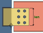
Length: The distance (in the primary dimension " Units " or other units ) from the component's origin to the plate's edge. The plate's length is parallel with the component's X axis
|
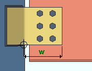
Width: The distance (in the primary dimension " Units " or other units ) from the component's origin to the opposite edge of the plate. When the " Connection type " is ' Bent plate ', this is the width of the leg of the bent plate that connects to the supported member. A shear plate's width is perpendicular to the component's X axis
|
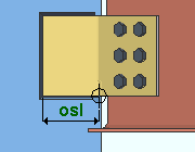
Outstanding leg: The width (in the primary dimension " Units " or other units ) of the outstanding leg of a bent plate. If the " Connection type " is ' Shear plate ', this option is disabled -- grayed out.
|
Radius: The inside radius (in the primary dimension " Units " or other units ) of the bend of the plate, when the " Connection type " is ' Bent plate '. When the " Connection type " is ' Shear plate ', this option is disabled -- grayed out.
Plate thickness: The thickness of the plate material (in the primary dimension " Units " or other units ).
page 1 | contents | add surfaces connection | top
------ Component reference point ------
X offset: A positive or negative (-) distance (in the primary dimension " Units " or other units ) by which the origin point is offset from the work point along the component's X axis when you press " OK ". The next time you edit the surface component, the option is set to ' 0 ' -- making an entry to this field will further move the origin point the component by that distance when you press " OK ."
The location of the surfaces connection component's origin and the direction of its X axis depends upon the end of the supported member's face that the component's work point is located. It doesn't matter whether the plate is placed on the near side or the far side of the supported member -- when you are facing one of its surfaces, any plate you add to the side on your left (or right) at that face will have the same orientation.
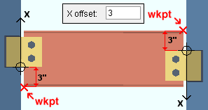
Both components bolt to the same face of the beam web, but are on opposite ends of the member.
page 1 | contents | add surfaces connection | top
------ Connection to supporting / supported ------
Connection type: Welded or Bolted . When the " Connection type " is ' Shear plate ', the connection to supporting is set to ' Welded ' and this option is disabled -- grayed out.
Weld size: The distance (in the primary dimension " Units " or other units ). This applies when the " Connection type " is ' Welded '.
If the " Connection type " is ' Bolted ' :
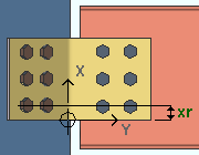
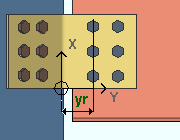
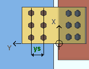
X reference offset: The distance (in the primary dimension " Units " or other units ) along the hole group's X axis from the component's origin to the center of the first bolt column.
|
Y reference offset: The distance (in the primary dimension " Units " or other units ) along the hole group's Y axis from the component's origin to the center of the first bolt row.
|
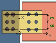
X spacing: The center to center distance (in the primary dimension " Units " or other units ) along the hole group's X axis between bolt columns.
|
Y spacing: The center to center distance (in the primary dimension " Units " or other units ) along the hole group's Y axis between bolt rows.
|
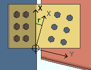
Hole group rotation: A positive or negative (-) number of degrees. A hole group consist of all the holes and bolt columns on a shear plate, or on a single leg of a bent plate. Hole groups on a surfaces connection component rotate about the component's origin point.
|
' 0 ' (zero) degrees sets each of the hole group's rows parallel to the component's X axis.
A ' positive number ' of degrees rotates the hole group clockwise.
A ' negative number ' of degrees rotates the hole group counterclockwise.
Note: If, after you Set Hole Group Reference Point , you change the entry to " Hole group rotation ," the hole group reference point returns to the surfaces connection component's origin point, the hole group direction is reset, and the hole group is rotated about the component's origin point. Set Hole Group Reference Point , therefore, has no effect on " Hole group rotation ."
Rows: The number of bolt rows.
Columns: The number of bolt columns.
Bolt diameter: The diameter (inches or mm) of the shank of the bolt. This is also the " Diameter " of the bolt on its edit window. The bolt diameter entered here, together with the " Hole type " entered below, set the diameter of holes through the plate.
| diameter |
|
The bolt diameter entered here, together with the " Hole type " entered below, set the diameter of holes through the plate.
Note: The diameters that you can enter here are not limited to those at Home > Project Settings > Job > Bolt Settings > the " Available bolt diameters ." The bolt diameter entered here, together with the " Hole type " entered below, set the diameter of holes through the paddle plate.
Hole type: Standard Round or Short Slot or Oversized Round or Long Slot . The " Hole type " used in the plate.
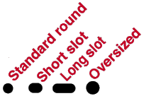
Matching holes will be generated in the supported or supporting members so that the plate material can be bolted to that member. The matching holes in the member will be standard round even if " Short slot " or " Long slot " or " Oversized " is used.
See Table J3.3 or Table J3.3M ( AISC Thirteenth Edition , p. 16.1-105) for information on how holes of particular types are sized with respect to the input bolt " Diameter ."
Slot rotation: A positive or negative (-) number of degrees. This is also the " Slot rotation " of the hole on its edit window. This slot rotation applies only when the hole " Hole type " is ' Short slot ' or ' Long slot '. Slot rotations can be modeled to a precision of 0.1 degree.
' 0 ' (zero) degrees sets the length of the slot perpendicular to the hole group's direction (Y axis).
A ' positive number ' of degrees, when the " Connection type " is ' Bent plate ', rotates the slot clockwise. When the " Connection type " is ' Shear plate ', it rotates the slot counterclockwise
A ' negative number ' of degrees, when the " Connection type " is ' Bent plate ', rotates the slot counterclockwise. When the " Connection type " is ' Shear plate ', it rotates the slot clockwise.
Slot length: The distance (in the primary dimension " Units " or other units ). This slot length applies only when the hole " Hole type " is ' Short slot ' or ' Long slot '. When you first choose a slot hole type, or, when you change " Bolt diameter ," the length is populated automatically. Then, if you like, you may enter another value.
See Table J3.3 or Table J3.3M ( AISC Thirteenth Edition , p. 16.1-105) for information on how holes of particular types are sized with respect to the input bolt " Diameter ."
page 1 | contents | add surfaces connection | top
