 Hole - Set Reference Point Command
Before using this tool, go to a surface that is in the same plane as the hole group you want to perform this operation on.
- Step-By-Step
- Examples
- Related Tools
1 . Preselect a hole to enable the Holes contextual page and click the Hole - Set Reference Point icon found in the Drawings section. Skip step 2.
Alternative : Invoke Hole - Set Reference Point using the Find Tool by searching the command name and clicking the Hole - Set Reference Point icon, which is pictured above. Proceed to step 2.
Learn more about alternative methods for launching commands.
2 . Select any hole in the hole group.
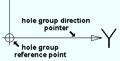
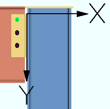
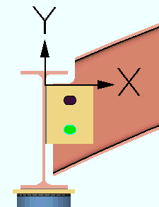
3 . The status line prompts, "Verify hole group reference location and direction ." Axes symbols (arrows) marked X and Y appear on screen along with Yes - No mouse bindings. The origin of the axes is the hole group reference point. The Y axis is the hole group direction.

Alternative 1 : Left-click ( Yes ) if you want both the reference point and direction to remain as they are shown on screen. This choice ends the command.
Alternative 2 : Right-click ( No ) if you want to change either the hole group reference location or direction shown on screen.
4 . The status line prompts, "Locate hole group reference point." The Locate options become active along with the Locate- Pan -Return mouse bindings.
Alternative 1 : Move the mouse pointer (
) so that the point location target snaps to the place on screen where you want the reference point, then left-click ( Locate ). Go to step 5.
Alternative 2 : Right-click ( Return ) to cancel the command. The reference point remains unchanged.
5 . The status line prompts, "Locate hole group direction point: " A reference point symbol identifies the location of the reference point.
Alternative 1 : Move the mouse pointer (
) so that the point location target defines the direction you want this hole group to be dimensioned from with respect to the reference point, then left-click ( Locate ). Go to step 6.
Alternative 2 : Right-click ( Return ) to cancel the command. The hole group reference point and direction remain unchanged.
6 . The status line prompts, "Verify hole group reference location and direction"Yes-Nomouse bindings become active.
Alternative 1 : Left-click ( Yes ) to keep both the reference point and direction as shown on screen and end the command.
Note: The changes made to the hole group reference location and direction are automatically applied to all members or materials with the same mark. You will not be prompted by the Change All Options window.
Alternative 2 : Right-click ( No ) if you want to change either the reference point location or direction. The command repeats Step 5.
- Add Hole
- Hole Match
- Hole Edit window
- Hole Erase
- Hole Move
- Hole Group Move
- Hole Properties
- Display Options (toggle the 3D display of holes in Modeling)
- 3D holes (about holes in Modeling)
- Important information about 3D holes (topic)
- Preselection modes & in-tool selection modes
- Selection filter
- Hole group rotation (corresponds to hole group X axis)
- Slot rotation (affected by hole group orientation)


