The Bolt Edit window ( Drawing Editor )
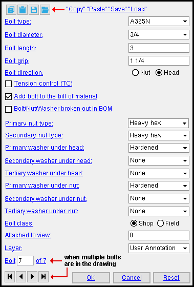
Options on this window are read-only if you are editing a bolt that is not on a comment layer and your current drawing is not a crane placement drawing . If your current drawing is a crane placement drawing, you can add or edit objects on non-comment layers as well as on comment layers. Instructions on this page assume you are NOT in a crane placement drawing.
To open this window :
- Add Bolt
- Bolt Edit or double-click a bolt
- Bolt Edit (multiple)
page 1 | contents | bolts | top
![]() " Copy " " Paste " " Save " " Load " buttons
" Copy " " Paste " " Save " " Load " buttons
page 1 | contents | bolts | top
Bolt type: A325NG or A325S or A325SX or etc.
Setup: The bolt types that appear as options on this list box (
) come from the Bolt Specifications in Job Options.
Bolt diameter: The diameter (inches or mm) of the shank of the bolt you are editing or adding.
diameter ![]()
To make an entry: You can type in a diameter, or select a bolt diameter from the combo box's menu (
). Both imperial and metric bolts can optionally be used in the same Job. Diameters listed on the menu come from Home > Project Settings > Job > Bolt Settings > the " Available bolts " list.
Defaults: The default value shown here for the first time you do an Add Bolt operation is the " Default non-moment bolt diameter for this job " entered in Job Options . For subsequently added bolts, the default is the diameter of the last-added or last-edited bolt -- see " OK ."
Bolt length: The distance (in the primary dimension " Units " or other units ) from inside the bolt head to the tip of the bolt shaft.
length ![]()
Note: Head thickness is not included in the calculation of a bolt's length because head thickness may vary from manufacturer to manufacturer or even from batch to batch.
Bolt grip: The inside distance (in the primary dimension " Units " or other units ) between the bolt head and nut. If the bolt has washers, then the distance is the inside distance between the washers.
grip ![]()
Bolt direction: Head or Nut . This applies only when you have added a bolt by locating twice at the same location.

|
|
| head | nut |
Select ' Head ' if you want the head of the bolt to be shown on the drawing.
Select ' Nut ' if you want the nut to be shown.
If this box is checked (
), the bolt will be designated as a tension control bolt. A TC bolt is a bolt with a splined end extending beyond the threaded portion of the bolt. The bolt is installed using a special wrench that removes the splined end when the bolt is tightened to the proper tension.
If the box is not checked (
), the bolt bolt will be designated as a non tension control bolt.
Add bolt to the bill of material: N/A . An option to add a bolt to a bill of material is not applicable in SDS2 Site Planning. Consequently, such an option is not ever shown. To add a bolt to a drawing's bill of material, a user can use a full-featured SDS2 program .
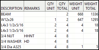
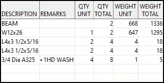
Bolt/Nut/Washer broken out in BOM: ![]() or
or ![]() . This option can apply to any bolt that you can review on a member detail. Normally only shop bolts are drawn on member details.
. This option can apply to any bolt that you can review on a member detail. Normally only shop bolts are drawn on member details.
|
||||||
| Screen shots of the BOM are from the bill editor . |
If this box is checked (
), then the bolt you are reviewing is called out in three separate lines in the " Description " column in the member bill of material (BOM). The first line is for the bolt's nut(s) (e.g., 3/4 NUT ). The second line is for the bolt's washer(s) (e.g., 3/4 WASHER ). The third line is for the bolt (e.g., 3/4 Dia A325 ).
If the box is not checked (
) for all bolts in the BOM quantity of bolts, then those bolts are called out as a single line item. Washer information is called out in the " Remarks " column. If more that one nut is associated with the bolt, the extra nut is also called out in the BOM's " Remarks " column.
Defaults: Home > Project Settings > Fabricator > Bolt Detailing Settings > " Bolt/Nut/Washer broken out in BOM sets the default for all bolts in the model. Users in a full-featured SDS2 program can override that default using " Bolt/Nut/Washer broken out in BOM " on the Bolt Edit window in Modeling . The default choice made here matches the choice made in Modeling .
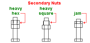
Primary nut type: None or Heavy hex or Heavy square or Jam . The nut that is in the "primary" position is the nut that is closest to the steel being fastened. It is the inside nut.
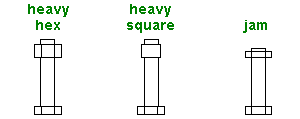
Secondary nut type: None or Heavy hex or Heavy square or Jam . The nut that is in the "secondary" position is the outside nut..
Primary washer under head: None or Flat or Hardened or Bevel or Plate (square plate) or Load (direct tension indicator). The washer under the head of the bolt that is in the "primary" position is the washer that is closest to the steel being fastened.
washer under head ![]()
| type | shape | BOM | setup thickness |
| flat |
|
FL | " Flat washers " |
| hardened |
|
HD | " Hardened washers " |
| bevel |
|
BVL | " Bevel washers " |
| square
plate |
|
PL | " Plate washers " |
| direct tension indicator |
|
DTI | " Direct tension indicator " |
Secondary washer under head: None or Flat or Hardened or Bevel or Plate (square plate) or Load (direct tension indicator). Same as " Primary washer under head ," except that this washer is placed in the secondary position.
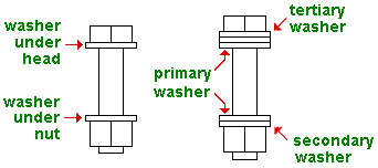
Tertiary washer under head: None or Flat or Hardened or Bevel or Plate (square plate) or Load (direct tension indicator). Same as " Primary washer under head ," except that this washer is placed in the tertiary position.

Primary washer under nut: None or Flat or Hardened or Bevel or Plate (square plate) or Load (direct tension indicator). The washer under the nut that is in the "primary" position is the washer that is closest to the steel being fastened.
washer under nut ![]()
| type | shape | BOM | setup thickness |
| flat |
|
FL | " Flat washers " |
| hardened |
|
HD | " Hardened washers " |
| bevel |
|
BVL | " Bevel washers " |
| square
plate |
|
PL | " Plate washers " |
| direct tension indicator |
|
DTI | " Direct tension indicator " |
Secondary washer under nut: None or Flat or Hardened or Bevel or Plate (square plate) or Load (direct tension indicator).

Tertiary washer under nut: None or Flat or Hardened or Bevel or Plate (square plate) or Load (direct tension indicator).

|
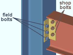
In the model , shop and field bolts can be displayed in different colors. Setup for this is done on the Member, Material, Bolt and Weld Colors window. |
' Shop ' bolts are bolts that are to be applied in the shop.
' Field ' bolts are sometimes referred to as "site bolts."
Also see: Bolt " Class " on the Bolt Edit window in Modeling .
Attached to view: A number designating the view that this 2D bolt is attached to. This applies mainly to member details , since member details are likely to show more views than submaterial details , the only other type of drawing on which you might find multiple views. For instance, a column detail may have a view of face A, face B and face C. It may also have various section views (Section A-A, Section B-B, Section C-C). All graphical objects that are in a particular view are assigned the same number.
Assigning the correct number to an object (line, weld symbol, label, etc.) provides maximum compatibility when the comment layer you add that object to is viewed or printed in a full-featured SDS2 program .
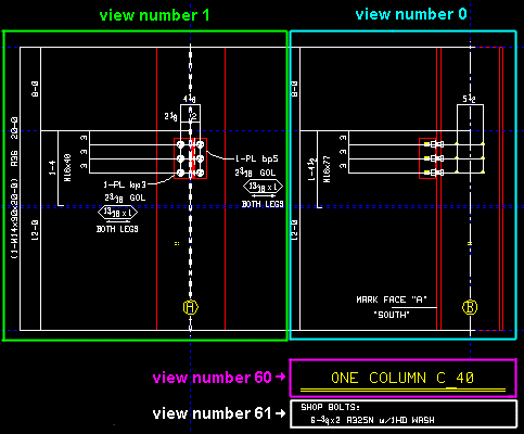
To show a view's number, you can add the X-Y-Z Display to your toolbar.

In the Drawing Editor , the X-Y-Z Display shows the view number that the point location target (
) is over.
Layer: Any drawing layer (any layer with a " Name ") in your current drawing. This is the drawing layer that the bolt you are adding or editing will be drawn on after you press " OK " to close this window. If that layer happens to be a hidden (not " Shown ") layer, the bolt will disappear after the first Redraw .
![]()
If the layer listed here is a non-comment layer: Options on this window are read-only .
If this window is editable: You can only select a comment layer from the list box's selection menu (
).
Defaults: For an Add Bolt operation, the default selection (
) will be a comment layer that is automatically created for you. Or, if you so choose, you can select a comment layer on the layer selection tool before you begin the add operation. For an Edit Bolt operation, the default selection is the layer that the bolt is currently on.
page 1 | contents | bolts | top
For Edit Bolt operations on comment layers :
Bolt _ of __( not applicable to Add Bolt or multiple edit or bolts on non-comment layers ): The number of the one bolt you are editing and the total count of all bolts in your current drawing. You can use the VCR buttons to select a different bolt that is on a comment layer and edit it while still on this window. When a bolt on a shown layer is selected, it is displayed in green. The selected bolt must be on a shown layer for it to be shown.
|
|
| VCR buttons (first-previous-next-last) for selecting a bolt to edit. |
Note: If you change one bolt, then select a different bolt number, the first bolt remains changed even if you press " Cancel " on this window.
page 1 | contents | bolts | top
Possibility #1 :
press the " OK " button if this window is for review only
(if you are editing a bolt that is not on a comment layer ).
Possibility #2 :
if you are adding or editing a bolt on a comment layer,
this window shows the following buttons:
![]()
![]()
![]()
"OK" (or the Enter key) closes the window and completes the Bolt Add or Bolt Edit operation.
Defaults: When you press " OK ," the settings on this window -- except mixed entries -- become the default settings for the next bolt you Add during this session of the Drawing Editor . Even if all you do is double-click a bolt that is on a comment layer and press " OK " without making any changes on this window, this window's settings become the defaults for the next-added bolt. The settings on this window do not become the defaults for new bolts if you press " Cancel " to close this window (unless you used the " Bolt _ of __ " widget).
"Cancel" (or the Esc key or the ![]() button) closes this window without saving any of the changes you have made. " Cancel " only cancels the changes made to the bolt whose number is currently selected in the " Bolt _ of __ " widget.
button) closes this window without saving any of the changes you have made. " Cancel " only cancels the changes made to the bolt whose number is currently selected in the " Bolt _ of __ " widget.
Tip 1: Although " Cancel " does not cancel all changes you have made on this window if you have edited more than one bolt, Undo does undo all those changes.
Tip 2: If you double-click a bolt that is on a comment layer just to review it and don't want to set the defaults for to-be-added bolts, the best way to close this window is to press " Cancel. "
"Reset" undoes changes made to the bolt currently selected in the " Bolt _ of __ " widget. The window remains open.
