The Rolled Section Material window ( Modeling ) (read-only)
Settings on this window are in additon to the settings applied in the local shape file to the W , L , C , pipe , TS , WT or other type of " Section size " that is selected on this window.
Piecemark: The submaterial piecemark ( up to 61 characters ) for the rolled section whose specifications you are reviewing.
Tip: For the current quantity of materials that have been assigned this piecemark, see the " Current quantity " listed on this material's General Information window .
Also see: When a full-featured SDS2 program assigns a submaterial piecemark, it names the mark by using the piecemarking prefixes for "channels," "angles," "pipe," etc., as the case may be.
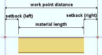
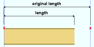
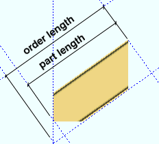
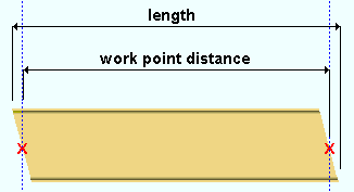
Order length: The distance before end cuts are made measured (in the primary dimension " Units " or other units ) from the furthest point on the material's left end to the furthest point on the material's right end. This dimension is measured parallel with the material's longitudinal axis ( X material axis ).
Part length: The distance (in the primary dimension " Units ") parallel with the X axis of the material from the furthest point on the material's left end (first work point end) to the furthest point on the material's right end. Unlike the " Order length ," this distance is measured after end cuts are made to the material. In most cases, the " Part length " and " Order length " will be exactly the same. Two special cases are described below:
Special case 1 : The end cut in this example is a " Clip web ." You can get this cut when you select ' Bolt to Floor ' as the " End condition " on a stair stringer.
Special case 2 : Combining a " Web cut angle " and a " Cope " on the same end of a rolled section is another way to cause the " Part length " and " Order length " to be different.
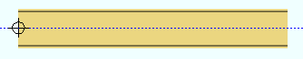
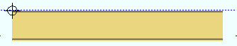
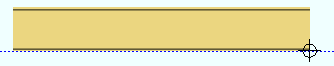
Work point distance: The distance (in the primary dimension " Units " or other units ) between the work points of this rolled section.
Angle of twist: 0 (zero) degrees or the positive or negative (-) number of degrees of twist about the longitudinal axis ( X material axis ) of the rolled section.
' 0 ' (zero) means the material is not twisted.
If a ' number of degrees ' is shown here, the right end is rotated that number of degrees, while the left end remains fixed. Entries may be between -3600 and 3600 degrees. Twists can be as little as .06 degree. Assuming you are looking from the right end toward the left end of the material, a positive entry rotates the material counterclockwise.
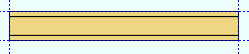
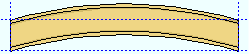
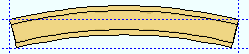
Rolling operation: None or Camber or Weak axis or Strong axis . The center of curvature for each of these choices (except ' None ') is midway between the left and right ends of the rolled section.
None
Camber
Weak axis
Strong axis
' None ' means the rolled section is straight (not curved).
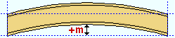
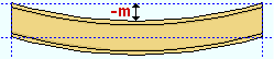
' Camber ' indicates parabolic bending along the strong axis of the rolled section with the ends fixed. The " Mid-ordinate " sets the offset at mid-span and the direction (+ or -) of that offset.
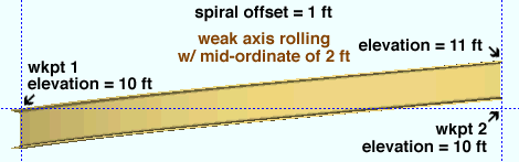
' Weak axis ' or ' Strong axis ' rolling indicates bending that is circular. The two ends of the rolled section are not fixed; that is, if the ends were vertical before the operation, they may not be vertical afterwards. The " Mid-ordinate " or " Included Angle " or " Rolling radius " sets the offset at mid-span and the direction (+ or -) of that offset. A " Spiral offset " may also be set.
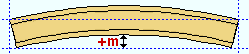
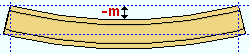
Mid-ordinate: The positive or negative (-) distance (in the primary dimension " Units " or other units ) that the rolled section is offset at mid-span as a result of a " Rolling operation " of ' Camber ' or ' Strong axis ' or ' Weak axis '.
Camber with a positive mid-ordinate( +m )
Camber with a negative mid-ordinate( -m )
Weak axis rolling with a positive mid-ordinate (rolling toward the near side)
Weak axis rolling with a negative mid-ordinate (rolling toward the far side)
Strong axis rolling with a positive mid-ordinate( +m )
Strong axis rolling with a negative mid-ordinate( -m )
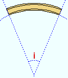
Included angle: The positive or negative (-) number of degrees that defines the angle of curvature when the " Rolling operation " is ' Strong axis ' or ' Weak axis '.
i = included angle. Extrapolate a circle from the inside curvature of the material, then draw a line along each end of the material. The lines will meet at the center of the imaginary circle, and their included angle is the angle entered here.
If the left end of the rolled section is to your left: A ' negative (-) angle ' makes the center of the rolled section lower on the screen than its two ends. A ' positive angle ' makes the center of the rolled section higher on the screen than the two ends.
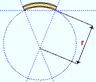
Rolling radius: A positive or negative distance (in the primary dimension " Units " or other units -- up to +/- 120,000 inches) that defines the amount of curvature of the rolled section when the " Rolling operation " is ' Strong axis ' or ' Weak axis '. The smaller the " Rolling radius " (+ or -), the greater the curvature.
r = rolling radius. If you were to extrapolate a circle from the inside curvature of the material, the distance from any point on the inside curve of the top/bottom flange to the center of the circle is the distance entered here.
Spiral offset: The positive or negative (-) distance (in the primary dimension " Units " or other units ) that the right end of the rolled section is offset from its original work point. The left end of the rolled section will remain fixed. This applies when the " Rolling operation " is ' Weak axis ' or ' Strong axis '.
For a rolled section whose workline is in the work plane of a plan view: A ' positive distance ' raises the right end. A ' negative (-) distance ' lowers the right end.
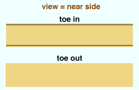
Toe direction: In or Out . This field applies to channel and angle materials.
' In ' signifies toe in. When facing the near side of the channel or angle (the near side is the side where the material's left end is to your left), the flange(s) of the angle or channel will point toward you when ' In ' is selected.
' Out ' signifies toe out. If you are viewing the near side of the channel or angle, the flange(s) will point away from when ' Out ' is selected.
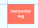
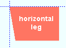
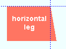
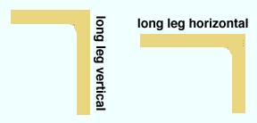
Long leg: Horizontal or Vertical . This field applies to angles with legs of unequal length.
' Horizontal ' specifies that long leg of the angle is horizontal.
' Vertical ' specifies that long leg of the angle is vertical.
Surface finish: None or Sandblasted or Red oxide or Yellow zinc or Gray oxide or Blued steel or Galvanized or Duplex Coating or Undefined 1 or Undefined 2 or Undefined 3 or Red oxide 2 or Any user added surface finish. This affects the colors of 'Solid ' members on erection views in the Drawing Editor . This also sets the color when "Output material color " is set to 'Surface finish ' for a VRML Export or a DWG/DXF Export . The "Color " ( not "Surface finish ") sets the color of this material in Modeling .
sand blasted
red oxide
yellow zinc
user surface finish 1
gray oxide
blued steel
galvanized
user surface finish 2
To assign a different surface finish, you can drop-down the current surface finish and select the one you want, or you can press the "file cabinet" browse button ( ) and double-click any surface finish that is on the list.
Auto or .
If this box is checked ( ), the material surface finish follows what is set on the member level.
If the box is not checked ( ), the material surface finish can be changed to whatever is available in the list of surface finishes. If the surface finish changes from what the member level has set, the auto checkbox will be unchecked automatically. When the auto check box is unchecked, the member edit window shows an information tag which notifies the user that an attached material is not following what was set on the member level.
Note 1:Submaterial piecemarkscan be split apart by surface finish. All surface finishes that do not have the 'Break Marks Material' checked on can be applied to any like material with out the material splitting. If the 'Break Marks Material' is checked on then only like materials with that specific surface finish can have the same piecemark, and because the submaterial marks differ so would the member's piecemark.
Note 2:When exporting a KISS file using "model" as the "Data source " surface finish data on the materials are compiled into the KISS download as follows, with a few exceptions (G=galvanized, N= none or sandblasted, P= others). Those exceptions are:
If the box for "Finish" routing in KISS export setup is set to a user routing
If the user has adjusted the Abbreviation for any of the default provided surface finishes
If you are using a user added surface finish
In these cases you will get what is provided in either the User routing, or the abbreviation field. For other exports it will always provide the abbreviation in the 'surface finishes' settings page.
Tip 1: "Surface area" is reported on the General Information window -- and this can be used to estimate the amount of coating required and its cost.
Tip 2: Changing "Steel grade " "Color " and "Surface finish " do not cause the plate to be regenerated. This means that, if you change those settings only, material fit operations such as a Fit Exact may, optionally, be preserved.
Color: The color of the rolled section when it is displayed in a solids form . Different colors may be assigned to materials that have the same submaterial piecemark . The color swatch next to the list box ( ) displays the color that is selected.
Setup: The default colors for member main materials and submaterials is set up on the Modeling Colors setup window.
Material setback: The positive or negative distance (in the primary dimension " Units " or in other units ) that the left or right end of the rolled section is displaced from its work point. A positive material setback makes the material shorter. A negative (-) material setback makes the rolled section longer.
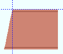
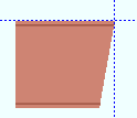
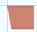
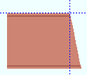
Web cut angle: A positive or negative (-) angle from 89 to -89 degrees.
left
right
left & right
left
right
-10 degrees
-10 degrees
0 degrees
10 degrees
10 degrees
Assuming that you are viewing the near side of the material, a ' positive angle ' is measured counterclockwise from a perpendicular bisector to the workline. A ' negative angle ' is measured clockwise from a perpendicular bisector to the workline. Any length that is added to a rolled section using this operation will be reflected in the " Material length " field.
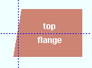
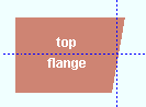
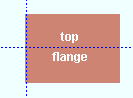
Flange cut angle: A positive or negative (-) angle from 89 to -89 degrees. The flange will be cut at this angle across its entire width.
wide flange
left
right
left & right
left
right
-10 degrees
-10 degrees
0 degrees
10 degrees
10 degrees
angle (or channel)
left
right
left & right
left
right
-10 degrees
-10 degrees
0 degrees
10 degrees
10 degrees
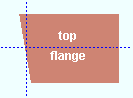
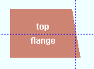
An entry of ' 0 ' (zero) designates that no web cut be made. Assuming that the left end of the top flange is to your left, a ' positive angle ' is measured counterclockwise from a perpendicular bisector to the flange center line. A ' negative (-) angle ' is measured clockwise from a perpendicular bisector to the top flange center line.
End-cut type: Standard cut or Square cut or Bevel cut or Mill cut .
If ' Standard cut ' is selected and the rolled section you are reviewing is member main material, the member detail will not be annotated with special cut instructions.
For a selection of ' Square cut ' or ' Bevel cut ' or ' Mill cut ' applied to a particular end of member main material, the member detail will include an annotation on how that end of the material is to be cut.
Moment connection web setback: The distance (in the primary dimension " Units " or other units ) that the web of this material is set back.
' None ' designates that no top/bottom flange cutting operation be performed on this material.
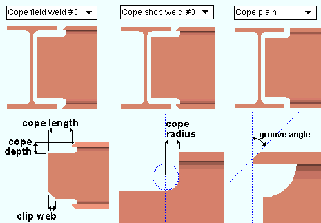
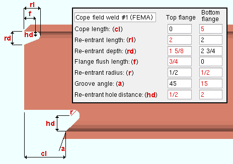
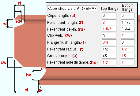
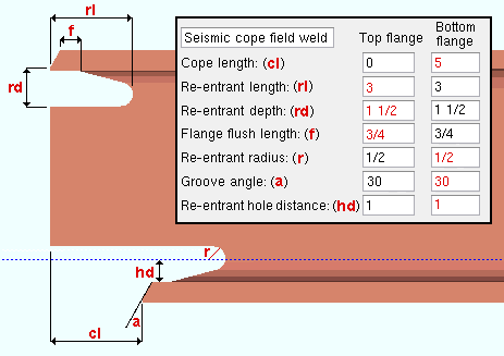
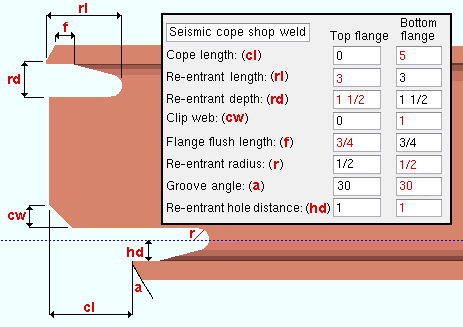
' Cope plain ' or ' Cope shop weld ' or ' Cope field weld ' designates weld preparation and/or a cut to remove part of the top/bottom flange plus part of the web. A ' Cope length ' and ' Cope depth ' of zero (0) for ' Cope shop weld ' or ' Cope field weld ' causes weld preparation without a coping operation.
" Cope length " is the distance parallel with the main material's longitudinal axis ( X material axis ) from the (left or right) end of the member to the flange. Entries must either be ' 0 ' or greater than or equal to '1/2' inch ('13' mm).
" Cope depth " is the distance from the top of the top flange (or bottom of the bottom flange) into the web of the material. The cope depth is measured parallel with the " Web cut " angle, or -- for ' Cope plain ', if the " Cope cut type " is ' Parallel to flange ' -- it is measured perpendicular to the flange. The " Cope depth " must be, at least, the flange thickness plus the " Cope radius ."
" Cope radiusSetup: operation." Cope plain " sets the curvature at the corner for a "Home > Project Settings > Fabricator > Member Detailing/Fabricator Options > the " Beams " section > " Cope radius ."
" Clip web " is an option when ' Cope shop weld #3 ' is the selected " Top/bottom flange operation ."
" Groove angle " sets the angle of the flange bevel (in degrees).
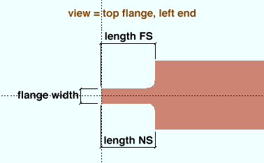
' Cut flange width ' designates two flange cuts, one on the near side and the other on the far side of the flange.
The ' Top/Bottom flange length NS ' is the distance from the (left or right) end of the material along the length of the near side of the top/bottom flange.
The ' Top/Bottom flange length FS ' is the distance from the (left or right) end of the material along the length of the far side of the top flange.
The ' Top/Bottom flange width ' is the flange width that remains after the NS and FS flange cuts are made.
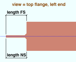
' Cut flange flush ' designates two flange cuts, one on the near side and the other on the far side of the flange, both cuts to the web. Entering zero (0) to the ' Length NS ' or ' Length FS ' field will mean that no cut is made at that location.
' Top/Bottom flange length NS ' - the distance from the (left or right) end of the material along the material's longitudinal axis ( X material axis ).
' Top/Bottom flange length FS ' - the distance from the (left or right) end of the material along the material's longitudinal axis ( X material axis ).
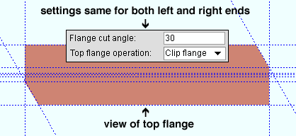
' Clip flange ' designates a linear cut from the flange to the radius of the web of the material at the angle designated by the field " Flange cut angle ."
In this example , the " Flange cut angle " is positive. The clip on the left end is on the near side of the flange. The clip on the right end is on the far side.
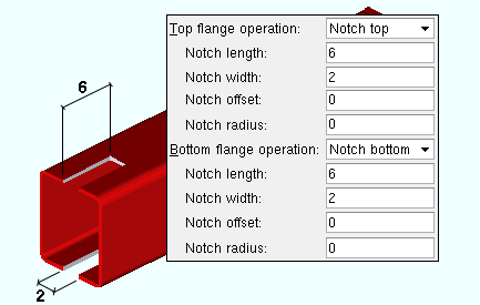
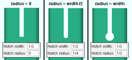
' Notch top ' or ' Notch bottom ' has distance entry fields for " Notch length " and " Notch width " and " Notch radius " and " Notch offset " that define the dimensions for a cut from the left/right edge of the HSS rectangular or HSS round material into the center of the material's top or bottom wall.
Enter a " Notch radius " other than ' 0 ' and set " Add holes " for ' in all radii ' in CNC Setup to have your CNC machine punch/drill the hole at the end of the slot.
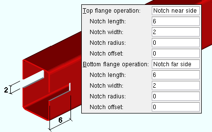
' Notch near side ' or ' Notch far side ' has distance entry fields for " Notch length " and " Notch radius " and " Notch width " and " Notch offset " that define the dimensions for a cut from the left/right edge of the HSS rectangular or HSS round material into the center of the material's near side or far side wall.
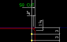
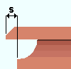
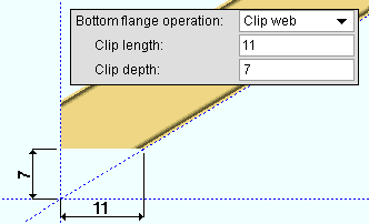
Clip web has distance entry fields for " Clip length " and " Clip depth ." This operation works well on channel sections, such as the stair stringer illustrated below.
A channel stair stringer with a cut generated by selecting ' Bolt to Floor ' as the " End condition ."
) and double-click any surface finish that is on the list.
), the material surface finish follows what is set on the member level.
), the material surface finish can be changed to whatever is available in the list of surface finishes. If the surface finish changes from what the member level has set, the auto checkbox will be unchecked automatically. When the auto check box is unchecked, the member edit window shows an information tag which notifies the user that an attached material is not following what was set on the member level.