 Exporting a DWG/DXF model
- General Overview
- Step-By-Step
- Tips and Tricks
- Related Tools
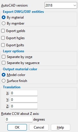
AutoCAD version: Unspecified (sets version to minimum), R10, R11/R12, R13, R14, 2000 - 2002, 2004 - 2006, 2007 - 2009, 2010, 2013, or 2018. This is the export version of the files that are output.
Note: After version R14, Autodesk began to name their versions after the years in which they were released.
Export DWG/DXF entities: By material or By member. When By material is selected, faces are grouped as materials. When By member is selected, faces are grouped as members, making it easier to select a member in its entirety in whatever program is used to view the imported DWG/DXF file.
Export welds: ![]() or
or ![]() . If this box
. If this box ![]() is checked, welds are output to the DWG/DXF file. If this option
is checked, welds are output to the DWG/DXF file. If this option ![]() is not checked, welds will not be included in the export file.
is not checked, welds will not be included in the export file.
Export holes: ![]() or
or ![]() . If this box
. If this box ![]() is checked, holes are output to the DWG/DXF file. If the box
is checked, holes are output to the DWG/DXF file. If the box ![]() is not checked, holes will not be included in the export file.
is not checked, holes will not be included in the export file.
Export bolts: ![]() or
or ![]() . If this box
. If this box ![]() is checked, bolts are output to the DWG/DXF file that will be generated when you press OK on the Export Model window. If the box
is checked, bolts are output to the DWG/DXF file that will be generated when you press OK on the Export Model window. If the box ![]() is not checked, bolts will not be included in the export file.
is not checked, bolts will not be included in the export file.
Separate by zone: ![]() or
or ![]() . If this box
. If this box ![]() is checked, a DWG/DXF layer will be generated for each zone that exported members can be found in. The layers will be named for their Zone Names. If the box
is checked, a DWG/DXF layer will be generated for each zone that exported members can be found in. The layers will be named for their Zone Names. If the box ![]() is not checked, members in the DWG/DXF file will not be grouped into layers.
is not checked, members in the DWG/DXF file will not be grouped into layers.
Note: Regardless of the choice made here, layers are output for the member type (beam, or column or etc.). This option simply allows you to output additional layers for zones.
Separate by sequence: ![]() or
or ![]() . If this box
. If this box ![]() is checked a DWG/DXF layer will be generated for each sequence that exported members can be found in. The layers will be named for their Sequence Names. If the box
is checked a DWG/DXF layer will be generated for each sequence that exported members can be found in. The layers will be named for their Sequence Names. If the box ![]() is not checked, members in the DWG/DXF file will not be grouped into layers.
is not checked, members in the DWG/DXF file will not be grouped into layers.
Note: Regardless of the choice made here, layers are output for the member type (beam, or column or etc.). This option simply allows you to output additional layers for sequences.
Output material color: Model color or Surface finish. When Model color is selected materials will be output in the color shown in the model. Generally, this will be the Color that is selected on their material edit windows or, if you are exporting while in Modeling, their status display colors. Select Surface finish to output materials in a color that matches the Surface finish that is selected for those materials on their material edit windows.
Translation: 0 or a positive/negative distance. Each member’s work points have specific global X, Y, and Z coordinates at both ends in the 3D model. To move all members in the exported file by a set amount along X, Y, and/or Z, enter that distance here.
0 for X and Y and Z exports a model with the same origin ( 0, 0, 0 global coordinate ) as the model in your current Job.
A positive distanceadds to the X, Y or Z coordinates of all exported members.
A negative distancesubtracts from the X, Y or Z coordinates of all exported members.
Rotate CCW about Z axis: Enter a positive or negative (-) degree value. A positive value rotates the DWG/DXF model counterclockwise about the global Z axis, while a negative value rotates it clockwise.
OK: Applies the changes made to settings on the window to the output of the DWG/DXF file.
Cancel: Click Cancel to keep only the settings that were active when you first opened this window; any changes made since then will be discarded and not used.
1. Click the Export Model icon, which is pictured above. The icon can be found on the Import/Export page > Model section.
Method 2: From the Home > Export screen, click Export Model in the 3D list.
Alternative: Invoke Export Model using the Find Tool by searching the command name and clicking the icon, which is pictured above.
Learn more about alternative methods for launching commands.
2. The status line prompts, "Select members". Select one or more members you want to be included in the export, then press the Enter key or right-click and choose OK on the context menu.
Alternative Right-click and select Cancel or press the Esc key to end the Model Export at any time.
3. The Export Model window opens, select DWG or DXF for the Export File format. Set the export properties and Destination to where you want the file to be exported and click OK. The model is now exported.
4. If the command was launched from the Home Screen, the Select Members for Downloading window opens, and a list of all members in the model are shown. Select the members you wish to include in the export and select OK. The model is now exported.

