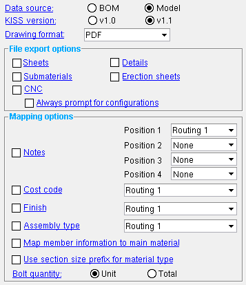
 The Kiss Export Setup setup window ( Job Settings )
- This window sets up Kiss Export and Tekla EPM Export , which are programs you can use to export data from the SDS2 3D model or from member bills of material. This window is accessible by users of SDS2 who have purchased an SDS2 KISS license.

Settings applied here , to the Kiss Export Setup window, are for your current Fabricator . A different set of Kiss Export Setup settings will apply when you " Change Fabricator ."
- To open this window
- " OK " " Cancel " " Reset "
Also see :
- Kiss Export (a program this window sets up)
- Tekla EPM Export (a program this window sets up)
- https://www.fabtrol.com/steelkiss-menu.html (more about the KISS format)
- http://www.fabtrol.com/images/stories/downloads/kiss_standard_v1_1.pdf (KISS standard)
- Exporting from your current Job (index)
page 1 | contents | home > export > click the gear | top
![]() To open Kiss Export Setup :
To open Kiss Export Setup :
Method 1 : Home > Export > click the gear (
) next to KISS Export or Fabsuite Export .
Password protection: If you have not purchased an SDS2 KISS licenses, you cannot open this window. Also, if a password has been set using the Change Setup Password utility, you can open this window only if you first enter that exact password.
page 1 | contents | home > export > click the gear | top
--- ---- General settings -------
Data source: BOM or Model .
Select ' BOM ' (bill of material) if you want the KISS file to include information added to member details using Edit Bill . ' BOM ' data does not include labor information (info in L lines -- click here for an example) or paint information (see " Surface finish "). Data comes from the bills of material of the members (or sheets) that you select in step 4 . Also, if you select by sheet (
Detail sheets ), the bill data for a member on a selected sheet is included in the export file only if " List in bill of material " is checked (
) for that member on the sheet.
Select ' Model ' if you want the data that is output to the KISS file to come from member and Shape files in the 3D model. To get L lines or paint information, ' Model ' must be selected. Also, ' Model ' must be selected and ' v1.1 ' must be " Kiss version " to get the part name. Unless you want user-entered information from the bills of selected members, this is the preferred choice.
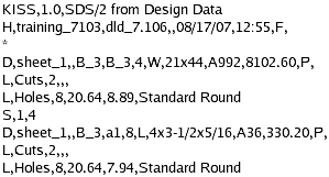
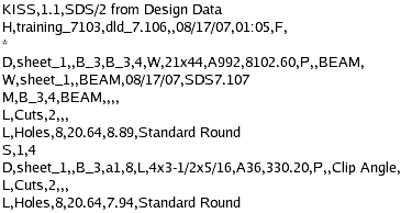
KISS version: v1.0 or v1.1 . Select the latest version that the software you are exporting to is capable of reading. The following examples are v1.0 and v1.1 .kss files of the same members (B_3) on the same sheet (sheet_1) with the same submaterial (a3). Notice that the v1.1 file provides more information.
| KISS v1.0 | KISS v1.1 |

|

|
' v1.0 ' outputs data on materials, holes, bolts, cuts, etc. Click here for an example.
' v1.1 ' gives you everything that v1.0 does, plus a part name and a cost code. Also, the Drawing Line "M" and Assembly Line "W" only appear in the v1.1 export. The part name for a member main material is "BEAM" or "COLUMN" or etc., depending on the member type. For system connection material, the part name is "Clip Angle" or "Gusset" or etc., depending on the connection. A routing may be mapped to the cost code when the box for " Cost code " is checked in " Mapping options " (below). Visit https://www.fabtrol.com/steelkiss-menu.html for examples of both the v1.0 and v1.1 KISS standards.
Note: To get the part name in the KISS file, you must select ' Model ' as the " Data source " as well as ' v1.1 ' as the " Kiss version ."
Drawing format: PDF or DWG or DXF or DXB or DNG . Choose the file format that you prefer. The next time you KISS Export or Tekla EPM Export using the same current Fabricator, drawings of the type selected under " File export options " will be output in this format, named after the original files, and given the appropriate extension.
| Format | Extension | Description |
| ' PDF ' | PDF stands for Portable Document Format. The file can be viewed using programs such as Adobe Reader and Bluebeam. | |
| ' DWG ' | .dwg | AutoCAD's native format. |
| ' DXF ' | .dxf | Stands for Drawing Exchange Format. It may be used for importing and exporting to various vector graphics programs. |
| ' DXB ' | .dxb | Stands for Drawing Exchange Binary format. It is a binary version of a DXF file. |
| ' DGN ' | .dng | Stands for Drawing file. |
page 1 | contents | home > export > click the gear | top
--- ---- File export options -------
Sheets: ![]() or
or ![]() .
.
If this box is checked , the KISS Export or FabSuite Export program outputs drawings of detail sheets to the Fabrication folder that is created when you export. The folder is found in a folder that is named after the " KISS folder name ." If you select by detail sheets ( step 4 ), only the sheets you select are generated. If you select by details, the sheets those details are on are generated. The sheets will be in the " Drawing format " specified above.
If the box is not checked , no drawings of sheets are output to the Fabrication folder.
Also see: step 1f .
If this box is checked , the KISS Export or FabSuite Export program outputs .dxf drawings of member details to the Fabrication folder that is created when you export. If you select by detail sheets ( step 4 ), only the details on those sheets you select are generated. If you select by details, only the details you select are generated.
If the box is not checked , no drawings of member details are output to the Fabrication folder.
Also see: step 1e .
If this box is checked , the KISS Export or FabSuite Export program outputs .dxf drawings of submaterials to the Part folder that is created when you export. If you select by detail sheets ( step 4 ), only submaterials on the details that are on those sheets you select are generated. If you select by details, only the submaterials that are on the details you select are generated.
If the box is not checked , the Part folder will be empty.
Also see: step 1g .
If this box is checked , the KISS Export or FabSuite Export program outputs erection sheets to the Erection folder that is created when you export.
If the box is not checked , the Erection folder will be empty.
Also see: step 1i .
If this box is checked , CNC data is output to the CNCData folder that is created when you export the kiss file. If you select by details ( step 4 ), only CNC data on the submaterials that are on the details you select are generated.
If the box is not checked , no CNC data is output to the CNCData folder.
Also see: step 1h .
Always prompt for configuration: ![]() or
or ![]() . This applies when "
. This applies when " ![]() CNC " is checked. In other words, it applies when you output CNC files.
CNC " is checked. In other words, it applies when you output CNC files.
If this box is checked , you are prompted (step 4d) to select the CNC configuration that you want to be used to format CNC files that you output.
If the box is not checked , the KISS Export or FabSuite Export program uses the currently selected " CNC Configuration " that is shown on the Computer Numerically Controlled window.
Note: If, for either of these choices, you select more than one configuration, a file for each configuration may be output for each piece. Output is to the CNCData folder.
Also see: Step 1h .
page 1 | contents | home > export > click the gear | top
------- Mapping options -------
Notes: ![]() or
or ![]() . Notes are output to the D line of the KISS file.
. Notes are output to the D line of the KISS file.
|
If the box is checked (
), you can select ' Routing 1 ' (default = " Mult. Cutting # ") or ' Routing 2 ' (default = " Labor Code ") or ' Routing 3 ' (default = " Job Cost Code ") or ' Routing 4 ' (default = " Remarks "). A " routing " is a list of user-defined information (routing definitions) that you can assign to materials. The selection made here sets the category of routing definitions assigned to materials that you want mapped to the KISS file.
If the box is not checked (
), no data is output to the notes category in the KISS file.
Cost code: ![]() or
or ![]() . Same as " Notes ," except that this outputs cost code information to the KISS file (v1.1 only). Cost code information is output to the D line and the M line in the KISS file. A maximum of 6 characters is allowed.
. Same as " Notes ," except that this outputs cost code information to the KISS file (v1.1 only). Cost code information is output to the D line and the M line in the KISS file. A maximum of 6 characters is allowed.
|
Finish: ![]() or
or ![]() . Finish is output to the D line of the KISS file.
. Finish is output to the D line of the KISS file.
|
If the box is checked (
), the KISS Export or FabSuite Export program maps data from the selected material routing definition. See " Notes " for information on selecting a routing definition.
If the box is not checked (
), " Surface finish " is output to the KISS file (G = galvanized; N = none or sandblasted; P = others).
Assembly type: ![]() or
or ![]() . Same as " Notes ," except that this outputs assembly type information to the M line of the KISS file.
. Same as " Notes ," except that this outputs assembly type information to the M line of the KISS file.
|
Map member information to main material: ![]() or
or ![]() . This applies when a box is checked for " Notes " and/or " Cost code " and/or " Finish ."
. This applies when a box is checked for " Notes " and/or " Cost code " and/or " Finish ."
|
|
If the box is checked (
), the KISS Export or FabSuite Export program maps member routing information along with material routing information.
If the box is not checked (
), the export program only maps material routing information.
Note: For " Cost code ," a maximum of 6 characters is allowed. Since the material routing is listed first, this means that if you have a material routing that is six characters along with a member routing, you will get only the material routing.
Use section size prefix for material type: ![]() or
or ![]() . This applies when ' Model ' is the " Data source ." It applies only to materials that originate in the local shape file .
. This applies when ' Model ' is the " Data source ." It applies only to materials that originate in the local shape file .
|
|
If the box is checked (
), the KISS Export or FabSuite Export program uses the section size prefix as the material type in line D. This is especially useful if you have re-named the " Section Size " in the local shape file , for example, to meet local naming conventions used in a particular nation or region. In the above example, the WPS material is a welded plate wide flange . Note: The KISS standard requires that the material type be a maximum of 3 characters. This means that if you enter a local shape file " Section Size " that is more than three characters, only the first three characters will be shown in the KISS file.
If the box is not checked (
), the export program uses the following designations: W for wide flange , S for S shape , MC or C for channel , L for angle , TS or HSS for tube , PI for pipe , WT for W tee , ST for S tee , CV for clevis , TB for turnbuckle , WWF for welded plate wide flange , and MI (miscellaneous) for other materials in the local shape file.
For materials not in Shapes Properties : The material type can be set using the " Description Prefixes " in Home > Project Settings > Fabricator > Member and Material Piecemarking > the " Prefixes " tab, but you must set the " Data source " to ' BOM '.
Bolt quantity: Unit or Total . This applies when ' Model ' is the " Data source " and you export a member with a quantity greater than one. In the following examples: The beam quantity is 2 . The first example shows unit quantity ( 8 shop bolts; 16 field bolts). The second example shows total quantity ( 16 shop bolts; 32 field bolts).
|
|
' Unit ' results in the KISS file reporting the field bolt quantity and shop bolt shop bolt quantity for only one member. No matter how many members there are under the selected piecemark, the reported shop/field bolt quantities will be for only one member.
' Total ' results in the KISS file reporting the field bolt quantity and shop bolt shop bolt quantity for all members under the selected piecemark.
page 1 | contents | home > export > click the gear | top
 To close KISS Export Setup :


"OK" (or the Enter key) closes the KISS Export Setup window and saves the settings on it to the current Fabricator . These options are applied the next time you KISS Export or Tekla EPM Export using that same current Fabricator. To change to a different Fabricator , Home > press "fabname" > double-click the Fabricator you want.
"Cancel" (or the Esc key or the
button) closes this window without saving any changes made to it.
"Reset" undoes all changes made to this window since you first opened it. The window remains open.
page 1 | contents | home > export > click the gear | top


