 Preliminary Load Planning
The Load Numbers and their member data can be exported as a report to a Microsoft Excel spreadsheet file (.xlsx).
This tool must be downloaded from SDS2 Toolbox and installed in order to use it.
- General Overview
- Step-By-Step
- Display Labels
- Tips and Tricks
- Related Tools
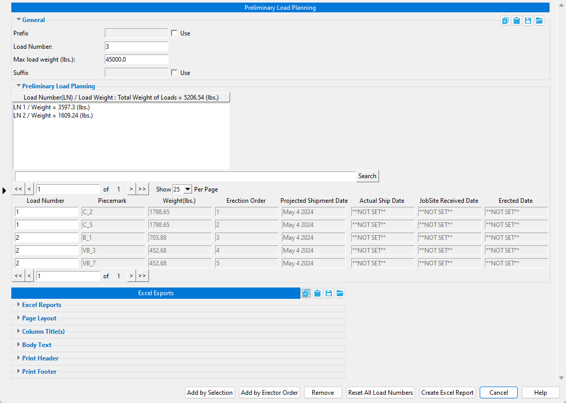
General
Prefix: The string character(s) (letters, numbers, symbols, and spaces) entered here are applied as a prefix to the Load Number.
When Use is checked
( , this field can be edited and its value will be applied to the Load Number.)
When Use is not checked
( , this field is read-only and its value will not be applied.)
Load Number: The numerical value entered here is the next available Load Number. This value will automatically increment to the next available value each time a new Load Number is added to Preliminary Load Planning.
Max load weight (units): The maximum weight allowed for each Load Number you add to Preliminary Load Planning. When selecting members, the Load Number will automatically increment to the next available value each time your member selection reaches the maximum load weight.
Suffix: The string character(s) (letters, numbers, symbols, and spaces) entered here are applied as a suffix to the Load Number.
When Use is checked
( , this field can be edited and its value will be applied to the next Load Number you add to Preliminary Load Planning.When Use is not checked
( , this field is read-only and its value will not be applied.
Preliminary Load Planning
Load Number(LN) / Load Weight: A list of each load number and its weight. The total weight of all load numbers is also shown. Load numbers can be selected or deselected in this field.
When one or more load numbers are selected in this field, their member data is shown in the data columns located below this field. The members in each selected load number are highlighted in the model and Zoom to Fit is automatically performed.
When all load numbers are deselected, all member data for all load numbers is shown in the data columns.
Search: This searches the member data that has been added to Preliminary Load Planning.
Note 1: A tooltip appears with examples of search instructions when you hover the mouse cursor over the search field. The Field Names are Load Number, Piecemark, Weight(units), Erection Order, Projected Shipment Date, Actual Ship Date, JobSite Received Date, Erected Date, Member Number, Sequence, Zone, Description, Elevation, Nearest Grid Intersection.
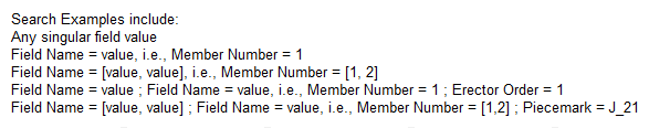
Search Examples you can copy/paste:
Member Number = 1
Member Number = [1, 2]
Member Number = 1 ; Erection Order = 1
Member Number = [1, 2] ; Piecemark = J_21Note 2: In order to perform a new search after performing one search, the search field must be reset. To reset the search field:
Step 1. Remove all contents from the search field.
Step 2. Click the Search button.
Load Number: The load number value that was added to the member's Load Number custom property.
Tip 1: You can manually change the value in the Load Number field by typing any string character (letters, numbers, symbols, and spaces) into the field. To manually change this value:
Step 1. Type in the new value in one of the fields.
Step 2. Press the Tab key or click a different Load Number field. Save Changes and Reset Changes buttons appear.
Step 3. When you are done making changes to the different Load Number fields, click the Save Changes button to keep the new value, or click the Reset Changes button to cancel the changes.
Tip 2: Clicking inside of each Load Number field zooms-to-fit and selects the member in the model, which highlights it using the color set for Primary selection surface (Home > Utilities > User and Site Options > Modeling).
Piecemark: The piecemark of the members.
Weight(units): The combined total weight of the member's main member material, attached submaterials, and attached bolts.
Erection Order: The erection order value that was added to the member's Order Of Erection custom property using Erector Order.
Projected Shipment Date: **NOT SET** or the month day year that is set in the Member Status Review window. The field in this window is read-only.
Actual Ship Date: **NOT SET** or the month day year that is set in the Member Status Review window. The field in this window is read-only.
JobSite Receieved Data: **NOT SET** or the month day year that is set in the Member Status Review window. The field in this window is read-only.
Erected Date: **NOT SET** or the month day year that is set in the Member Status Review window. The field in this window is read-only.
Additional columns that are disabled by default: (See Preliminary Load Planning Setup window)
Member Number: The member number of the members.
Sequence: The sequence of the members.
Zone: The zone of the members.
Description: The member type of the members (e.g., Beam, Column, Vertical Brace, etc.). .
Elevation: The elevation of the member. For columns and sloping members, the lowest elevation is displayed.
Nearest Grid Intersection: The nearest intersection of grid lines where a member's end is located. Preference is given to the grid intersection at a member's left end when a grid intersection is also near a member's right end.
Buttons
Add by Selection: Pressing this button allows you to select members in the model and add them to a Load Number. As you continue selecting members, a new Load Number is automatically created each time the Maximum load weight (units) is reached.
Note: When you select the first member, the Truck Load window appears to show you the current load number, the current weight added to that load, and the maximum weight that was set. The information on the Truck Load window continues to update as you select additional members.

Add by Erector Order: Pressing this button automatically adds members to a Load Number in the order of each member's Erection Order value. A new Load Number is created each time the Maximum load weight (units) is reached during this process. Members that do not have an Erection Order value are not added by this option. Before using this option, first use Erector Order to add Erection Order values to the members in your model.
Remove: Pressing this button allows you to select members in the model which have already been added to Preliminary Load Planning and remove them from the tool.
Reset All Load Numbers: Pressing this button will remove all Load Numbers from Preliminary Load Planning.
Create Excel Report: Pressing this button exports a report to a Microsoft Excel file (.xlsx). The Excel file is located at the file path set for Save Excel File As and opens automatically if Open Excel file after run is checked )
Cancel: Pressing this button closes the Preliminary Load Planning window.
![]() Copy, Paste, Save, Load buttons:
Copy, Paste, Save, Load buttons:
- The position of these "form" buttons on the window tells you what settings they apply to. Click here for more information.
- You can
 Copy the settings on this window, then
  Paste those settings to a different edit window of the same type.
- You can
 Save the settings on this window to a file stored in a global folder that is used by your current version of SDS2. Give the file a name that will help other users identify its purpose. You can
  Load a saved file to replace the settings on this window (except Piecemark) with the settings that are stored in the file you select.
- When editing multiple windows at the same time, Paste and Load replace mixed entries to a single field with a single entry. Copy and Save ignore fields with mixed entries, treating them as if they have no entry or do not exist.
Excel reports
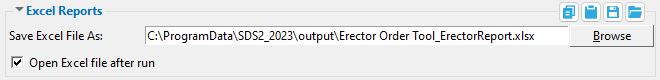
Save Excel File As: A file path. The file path and name of the XLSX file to be output. Type in the file path and name or press the Browse... button to set them.
Open Excel file after run: or .
If this box is checked
( , the XLSX file will open in your locally installed version of Microsoft Excel when you press Create Excel Report.If this box is not checked
( , the XLSX file will not open when you press Create Excel Report.
Page Layout
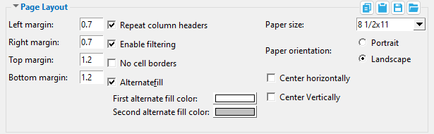
Left/Right/Top/Bottom margin: A distance in inches. This sets the distance from the edges of the page to the contents of the report. These options should not be confused with the header/footer margins.
LM = Left margin
RM = Right margin
TM = Top margin
BM = Bottom margin
If this box is checked
( , column headers are shown on the first page and on each subsequent page.If this box is not checked
( , column headers are shown on the first page only.
If this box is checked
( , sorting filters are applied to each column.If this box is not checked
( , sorting filters are not applied to each column.
If this box is checked
( , cell gridlines are not visible. This is not to be confused with cell borders in Microsoft Excel.If this box is not checked
( , cell gridlines are visible.

If this box is checked
( , the First and Second alternate fill color settings appear in the window and background shading with the First... and Second alternate color is applied to every other row.First alternate fill color: The color that you want applied to the background of alternate rows of cells after the title, starting with the first row. The button displays the selection that you make when you press it and pick a color on the Color window.
Second alternate fill color: The color that you want applied to the background of alternate rows of cells after the title, starting with the second row. This option is available when Alternate fill is checked
( . The button displays the selection that you make when you press it and pick a color on the Color window.If this box is not checked
( , no background shading is applied to the rows of cells and the First and Second alternate fill color settings do not appear in the window.
Paper size: 8 1/2 x 11 or 11 x 17 or D size sheet etc. This is the size of each page of the report.
Paper orientation:  Portrait or Landscape. This option orients each page of the report.

If this box is checked
( , the table will be centered horizontally between the page's left and right margins.If this box is not checked
( , the table on each page will be aligned against the left margin.
If this box is checked
( , the table will be centered vertically between the page's top and bottom margins.If this box is not checked
( , the table on each page will be aligned against the top margin.
Column Title(s)
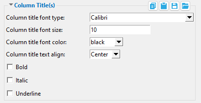
Column headers are placed at the top of each column below the title.
The title and column headers are affected by Column Title options.
Column title font type: A font that is installed on your workstation.
Column title font size: A size in points (typography).
Column title font color: A color. This changes the color of the text.
Column title text align: Center or Left or Right. This sets the alignment of the text.
If this box is checked
( , the text is shown with a bold font weight.If this box is not checked
( , the text is shown with a regular font weight.
If this box is checked
( , the text is shown with an italic font style.If this box is not checked
( , the text is shown with an regular font style.
If this box is checked
( , the text is underlined.If this box is not checked
( , the text is not underlined.
Body Text
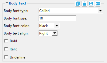
Body font type: A font that is installed on your workstation.
Body font size: A size in points (typography).
Body font color: A color. This changes the color of the text.
Body text align: Center or Left or Right. This sets the alignment of the text.
If this box is checked
( , the text is shown with a bold font weight.If this box is not checked
( , the text is shown with a regular font weight.
If this box is checked
( , the text is shown with an italic font style.If this box is not checked
( , the text is shown with a regular font style.
If this box is checked
( , the text is underlined.If this box is not checked
( , the text is not underlined.
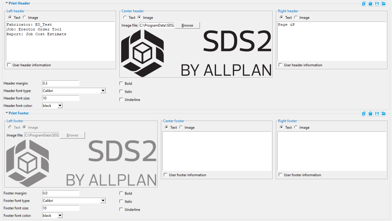
Print Header/Footer
|
|
| Headers appear at the top of each page. | Footers appear at the bottom of each page. |
Left/Center/Right header/footer: Text or Image
Choose
Choose
Note: The left footer is read-only by default and cannot be changed.
Image file: A file path. The location of an image file (GIF, JPEG, PNG, etc.). Type in the file path and name or press the Browse... button to set them. This option appears in the window when Image is chosen.
User header/footer information: or . This option is available when Text is selected.
If this box is checked
( , the text that you enter into the text field is added to the header/footer of each page.If this box is not checked
( , the text field becomes read-only and is either blank or populated with default information.
Header/Footer margin: A distance in inches. This determines the distance from the top of the page to the top of the header and from the bottom of the page to the bottom of the footer.
Header/Footer font type: A font that is installed on your workstation.
Header/Footer font size: A size in points (typography).
Header/Footer font color: A color. This changes the color of the text.
If this box is checked
( , the text is shown with a bold font weight.If this box is not checked
( , the text is shown with a regular font weight.
If this box is checked
( , the text is shown with an italic font style.If this box is not checked
( , the text is shown with a regular font style.
If this box is checked
( , the text is underlined.If this box is not checked
( , the text is not underlined.
1 . Click the Preliminary Load Planning icon, which is pictured above. The icon can be found on the Toolbox page.
Alternative: Invoke Preliminary Load Planning using the Find Tool by searching the command name and clicking the icon, which is pictured above.
Learn more about alternative methods for launching commands.
2 . The Preliminary Load Planning window appears. When you are done adjusting settings, do one of the following:
Option 1: Click the Add by Selection button. The Preliminary Load Planning window disappears so you can select members in the model. Left-click on a member to add a Load Number value to it. The Truck Load window appears showing the status of each Load Number created during this process. When you are done selecting members, press the Enter key or right-click and select OK.
Alternative: Press the Esc key or right-click and select Cancel to end the Add by Selection command. The Preliminary Load Planning window reappears.
Option 2: Click the Add by Erector Order button. This option automatically adds a Load Number value to all members that have an Order of Erection value. All other members are excluded. The Truck Load window immediately appears and shows the progress of the load assignment(s). Click OK on the Truck Load window to complete the operation.
Note: Before using this option, first use Erector Order to add Erection Order values to the members in your model.
3 . The Preliminary Load Planning window reappears and is now populated with Load Numbers and their members' data. When you are done adjusting settings in the window, click the Create Excel Report button to export a report to a Microsoft Excel file (.xlsx).
Alternative: Other tools can be used such as Remove and Reset All Load Numbers. Please see the General Overview tab for more information.
4 . When you are done using Preliminary Load Planning, click the Cancel button to close the window and end the command.
Note: You can run Preliminary Load Planning as often as needed to make adjustments and export the report.
Since the Load Number value is stored as a member custom property, you have the option to display it as a label in your 3D model and on your 2D erection diagrams.
Before following these steps, please open Preliminary Load Planning in your model to automatically activate the SDS2Fabricator member custom properties or manually activate them at Home > Project Settings > Job > Custom Properties > Activate Custom Properties.
1 . Enable the member custom property's Erection View Member Labels.
1a . Go to Home > Project Settings > Job > Custom Properties > Member Properties.
1b . Expand SDS2Fabricator and select SDS2Fabricator.LoadNumber from the Edit Schema list. Then click the Details... button.
1c . On the Add/Edit Schema Entry window, check the box (
2 . Set the Erection View Member Labels.
2a . Go to Home > Project Settings > Fabricator > Detailing > Erection View Member Labels.
2b . On the Label Positioning tab, set one of the rows to the SDS2Fabricator.LoadNumber Property name. Also set options of Perspective, Horiz. position, Vert. position, and Priority.
3 . In Modeling, open Display Options > General Settings and make sure Member custom properties is checked )
- In order to use the quick and easy Add by Erector Order option, first use the Erector Order to add Order of Erection values to members in your model.
- The Load Number value can be manually edited at the member level. On the member edit window, click the Properties button and look for the Load Number field.
- You can change the default settings of Preliminary Load Planning at Home > Project Settings > Job > Plugin Defaults > Command Plugin Defaults > Preliminary Load Planning Setup.
- Consider the number of columns in the chosen report when you select a Paper size and Paper orientation. If the report requires more columns than will fit on a page, an extra page will be generated to contain the rest of the columns.
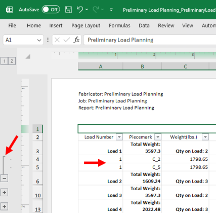
- You can expand the Load Numbers in the Excel report to see the member data. Click the + icons located beside the left margin to expand particular Load Numbers. Click the "2" button at the top-left corner of the spreadsheet to expand all Load Numbers at the same time. Click the "1" button to collapse them.

- Preliminary Load Planning Setup window (Project Settings)
- Erector Order (Command Plugin)

