Cope Report
| Note: A Cope Report cannot be generated for a material that is not coped or has no flange thinning operations -- you will get the error message " No end cuts or copes detected " or, if " Disable error checking " is checked, you will simply not get a report. |
About this report :
Step-by-step instructions :
- Step 1: Before generating the report
- Steps 2, & 3: Open Report Selection , select ' Cope Report ' , press "OK"
- Step 4: Select each material you want a report on
- Step 5: A report or error message is output for each material selected
CNC contents | CNC main menu | report selection
Example, description, setup :
B_6 is the name of the member whose main material is described in this report.
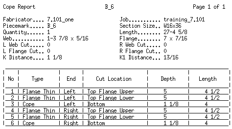
Description: A Cope Report identifies the location of cope and flange thinning operations. It can be used as a check list for such operations on wide flange , S shape , channel and angle material. A separate report is output for each material that you select. The report files are named for the selected materials and given a ".txt" extension.
Setup: You can output a Cope Report regardless of the " CNC configuration type " that is associated with your current " CNC configuration ." For example, you can output a Cope Report if the " CNC configuration type " is ' Cope Report ' or ' Peddinghaus Cope ' or etc. Be aware that the " CNC configuration type " you select does affect verification .
CNC contents | CNC main menu | report selection | top
Material information on the report :

Fabricator: The name of the current Fabricator that was active when you created the report. To change to a different Fabricator , Home > press "fabname" > double-click the Fabricator you want.
Job: The name of the current Job that was active when you created the report.
Piecemark: A member piecemark or submaterial mark .
If you generated this report by detail or detail sheet, the piecemark listed here is a member piecemark , and the fabrication information presented in the report is for the main material of that member.
If you generated your report by submaterial or gather sheet, the piecemark listed here a submaterial mark .
Section Size: The shape " Description " that conventionally describes the material.
| Section naming conventions : || wide flange || channel || angle || S_shape || |
Quantity: The total number of pieces of the member main material or submaterial whose member piecemark or submaterial mark is printed at the top of the report.
Note: There are cases where the member piecemark will have a different quantity than you would get were you to generate this same information for the submaterial mark. This happens when the main material for one member is exactly the same submaterial used for a different member (for instance, in a different sequence).
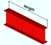
Length: The overall length of the material. This information comes from the 3D model .
Web: Web depth x web thickness . This information comes from the local shape file .
| d = depth |

|
tw = web thickness 
Flange: Flange width x flange thickness . This information comes from the local shape file .
tf = flange thickness 
L Web Cut: The angle (in degrees) of the cut to made on the left end of the material's web. 0 means no cut has been made. This information comes from the 3D model .
-10 degrees
 |
0 degrees
 |
10 degrees
 |
R Web Cut: Same as " L Web Cut ," except that this applies to the right end of the material.
-10 degrees
 |
0 degrees
 |
L Flange Cut: The angle (in degrees) of the cut to made on the left end of the material's flange. 0 means no cut has been made. This information comes from the 3D model .
-10 degrees
 |
0 degrees
 |
10 degrees
 |
R Flange Cut: Same as " L Flange Cut ," except that this applies to the right end of the material.
-10 degrees
 |
0 degrees
 |
K Distance: The distance from the bottom of the radius of the W , S , L or C section to the top of the flange. This information comes from the local shape file .
k = k distance
K1 Distance: The distance from the web center line to the edge of the radius of a W , S , C or L section.
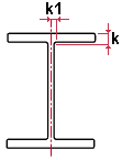 k1 = k1 distance
CNC contents | CNC main menu | report selection | top
Columns on the report :

No: The number assigned to the cut operation described on this line.
Type: Cope or Flange Thin (flange thinning) or Flange Flush NS/FS . This is the type of operation that is being performed.
End: Left or Right . This is the end of the material where the cut will be made.
Cut Location: The physical feature of the material that is to be cut. "Top flange upper" refers to the top flange, near side ; it is called "upper" instead of near side since web near side would be pointing up on the cutting machine's conveyor.
Depth: A distance that defines a different dimension depending on whether the type of operation is flange thinning or a cope..
For flange thinning , this is the width of the flange that remains after cuts have been made to both sides of the flange.
For a cope , this is depth of the cut as measured parallel with the depth of the material.
Length: The length of the cut as measured parallel with the material's length ( X material axis ) from the end of the material.
