"  Top Extension Plates " & "
  Bottom Extension Plates " connection design locks
| " |
|
|||
|
" ( the column must frame to a beam )  |
|
||
Connection Guide: Click here .
User Defined Connections: Settings that are locked (
) in a user defined connection file will automatically be locked on a member edit window for which that file is the " Input connection type ." You can, if you so choose, manually lock additional settings on the member edit window, and your changes will be retained, through multiple processes, so long as you do not change to a different connection then switch back to the original user defined connection.
Column Edit: To change a setting, first set it to locked (
). Related settings that are unlocked (
) may be updated, and the "
Left/Right end limit state " calculations will be updated. Settings that are locked (
) will not be changed by connection design , even if doing so might prevent a connection failure.
Connection design locks :
![]() Top Extension Plates /
Top Extension Plates / ![]() Bottom Extension Plates
Bottom Extension Plates
Plate dimensions
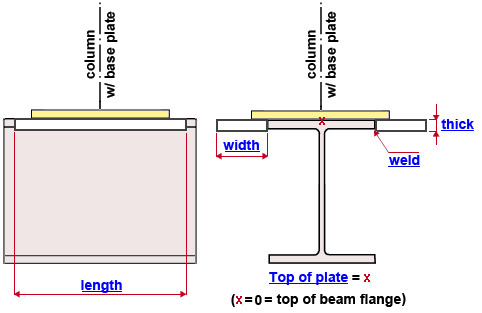
Plate length ( length ): The length of either of the flange extension plate's edges that are parallel with the beam's flange. This length applies to both the NS and FS flange extension plates. The length of the plate runs parallel with the length of the beam. See the example .
Plate width ( width ): The width of either of the flange extension plate's edges that are perpendicular to the beam's work line . This width applies to both the NS and FS flange extension plates. The width of the plate runs parallel with the width of the beam's flange. See the example .
Plate thickness ( thick ): The thickness of the flange extension plate. This thickness applies to both the NS and FS flange extension plates. See the example .
Top of plate: A positive or negative (-) distance .
For " Top Extension Plates ," 0 aligns the top of the flange extension plates with the top flange of the beam. A positive distance moves the extension plates down, toward the interior of the beam. A negative (-) distance moves the extension plates up, away from the beam, toward the top end of the column. In the example , " Top of plate " is set to 0.
For " Bottom Extension Plates ," 0 aligns the top of the flange extension plates with the bottom flange of the beam. A positive distance moves the extension plates up, toward the interior of the beam. A negative (-) distance moves the extension plates down, away from the beam, toward the bottom end of the column.
Weld to beam flange type ( weld ): Single bevel groove or Square butt groove or Single V groove or Double V groove or Single U groove or Double U groove or Single J groove or Double J groove or Groove w/ square back gouge . The weld type for shop welding the flange extension plates to the flange of the beam.

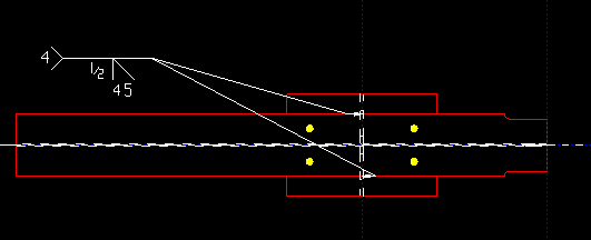
' Single bevel groove ' was selected as the " Weld to beam flange type " in order to generate this example from a detail showing extension plates welded to the top of a beam flange. . Weld to beam flange size ( weld ): The weld size for shop welding the flange extension plates to the flange of the beam.

This example is from a beam detail. To generate this example, ' 1/2 ' was entered as the " Weld to beam flange size ."


