 New Drawing
- General Overview
- Tips and Tricks
- Related Tools
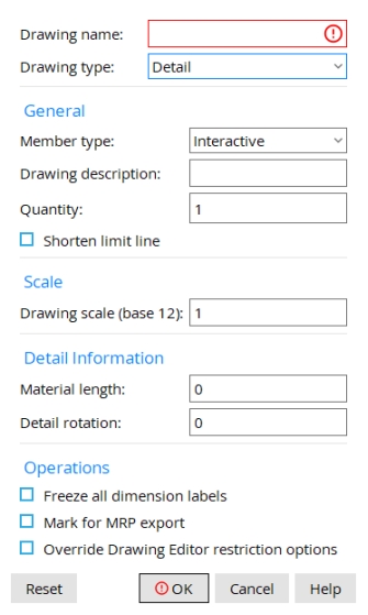
Drawing name: Type the name of the new drawing (maximum of 61 characters). This entry field cannot be left blank.
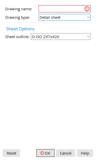
Drawing type: Details, Job standard details, Global standard details, Reference drawings, Detail sheet, Gather sheet, Erection sheet, Sheet outlines, Symbol drawing, and Global symbol drawing.
General
Member type: The type you select affects the sorting of members in the Sheet Loading Report. It does not affect the drawing.
Report Writer: PiecemarkDrawing.DetailTypeDescription
Drawing description: The string you enter here appears in line 1 of the drawing's bill of material.
Quantity: The number of pieces accounted for in the drawing's bill of material.
|
If this box
is checked, a shorten limit line is added to the new drawing. If you then place section views to the right of this line while the drawing is Unshortened, those views will automatically line up when the drawing is Shortened.
If the box
is not checked, a shorten limit line will not be added.
Report Writer: PiecemarkDrawing.ShortenPointLimitLine
Scale
Drawing scale (base 12 or base 10): The ratio between the dimensions of the new drawing and the real-world dimensions they represent.
(Base 12) indicates Imperial dimensioning. Enter the number of inches to represent 1 foot in the shop or construction site.
(Base 10) indicates Metric dimensioning. Enter the number of millimeters to represent 10 mm on the actual materials.
Detail Information
Material length: The length reported in the drawing's bill of material.
Detail rotation: The number of degrees of rotation (-180 to 180) of the object(s) you add to the drawing.
Operations
Freeze all dimension labels: or
If this box
If the box
If this box
If the box
Also see: Mark/Unmark for MRP export (Utilities > Change Options).
Override Drawing Editor restriction options: or
Sheet Options - Sheets
Sheet outline: Select one of the available sheet outlines from the list when creating a new Detail Sheet, Gather Sheet, or Erection Sheet.
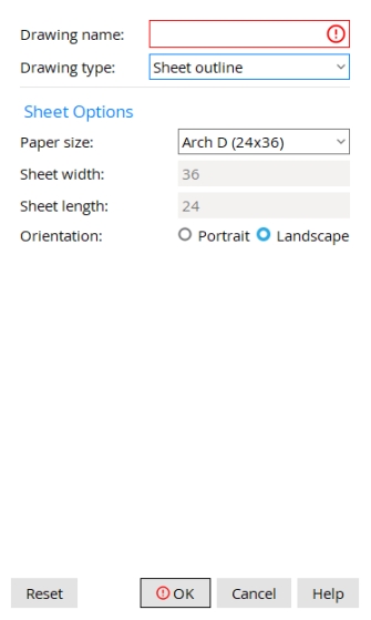
Sheet Options - Sheet Outlines
Paper size: Select one of the standardized paper sizes. These options automatically set the Sheet width and Sheet length. You can also select User-defined and set your own Sheet width and Sheet length.
ANSI: American National Standards Institute
ISO: International Standards Organization
ARCH: Architectural
Sheet width: Type the dimension of the new sheet outline's width (inches or mm). This is read-only unless the Paper size is set to User-defined.
Sheet length: Type the dimension of the new sheet outline's length (inches or mm). This is read-only unless the Paper size is set to User-defined.
Orientation:  Portrait or Landscape
Buttons
Reset undoes all changes made to this screen since you first opened it. The screen remains open.
OK (or the Enter key) opens the new drawing in your current Drawing Editor window. The creation of the new drawing is not complete until you Save it.
Cancel: (or the Esc key) closes the New Data Drawing window without creating the new drawing.
- New Submaterial details, Erection view drawings, and Connection cube drawings cannot be created using New Drawing. They must be created by auto detailing.
- Many of the options found on the New Data Drawing window can also be found and edited on the Drawing Data Panel after you create the new drawing.
- Red or yellow exclamation point icons
 or
or 
- User created details (Hide Items)
- Mark for FabTrol Export (Change Options)
- Save As
- Automatic detailing
- Drawing Data Panel

