 Tilt-up Panel ( Modeling > F2 >
  Concrete > " Tilt-up Panel" )
Tool summary :
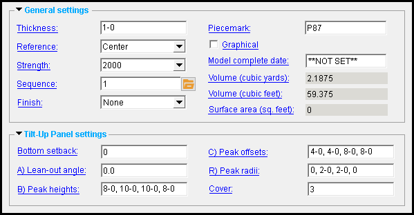
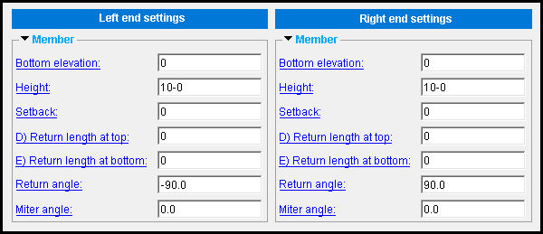
The Tilt-up Panel Edit window :
|
|
To open this window :
- With the Default filter selected, double-click a tilt-up panel member.
- Add a tilt-up panel .
On this page :
Also see :
- Modeling (where a tilt-up panel can be added or edited)
- Add Embed Assembly (add an assembly of embed plates or angles to a tilt-up panel)
- Add Panel-to-Panel Embed Assembly (add tilt-up panel-to-panel embed assemblies)
- Add Panel-to-Footing Embed Assembly (add tilt-up panel-to-footing embed assembiles)
concrete | F2 > concrete / rebar > | tilt-up panel | top
 To add a tilt-up panel :
A tilt-up panel can be added in Modeling by pressing F2 to open the Member Type Selection window, then double-clicking " Tilt-up Panel ."
Tilt-up panels are typically laid out in a plan view . Using the point locator INCL to locate the panel work points puts the bottom of the panel at the elevation of the plan view. If you want to use point locator options other than INCL , consider employing the Z filter toggle (
) to ensure that both located points snap to the reference elevation of the plan view. It is not required that the elevation of both points be at the elevation of the plan view, but you may prefer that they be at that elevation.
The member line of a tilt-up panel runs along the bottom of the panel.
As you add the tilt-up panel, select two points. The first point you locate establishes the left end of the panel. If you are adding multiple panels to enclose an area (for example, for use as a building shell), common practice is to lay out points counterclockwise around the perimeter of the area.
After you have located points as described above, the Tilt-Up Panel Edit window opens. Be sure to make correct entries to the fields for " Thickness ," " Reference ," " Bottom elevation ," and " Height ." Be aware that if you press " Cancel " on this window, you will end the tilt-up panel add operation without adding the panel. If you press " OK " to add the tilt-up panel, the resulting panel member will be associated with a group member .
Tip: If you have a concrete license, you can add rebar to the tilt-up panel using the Rebar System custom component.
concrete | F2 > concrete / rebar > | tilt-up panel | top
| Tilt-up panel properties |
------  General settings ------
Thickness: The horizontal distance (in the primary dimension " Units " or other units ) from the interior face of the tilt-up panel to the exterior face of the panel.
![]()
Changing the " Thickness " of a tilt-up panel does not reposition the member line of the panel. In other words, it does not reposition the representation of the outline of the tilt-up panel that is shown in stick form .
concrete | F2 > concrete / rebar > | tilt-up panel | top
------  Tilt-up panel settings ------
Reference: Center or Interior or Exterior . The choices you make for " Reference " affect the panel differently, depending on where points were added when the tilt-up panel was placed. Changing the " Reference " of a tilt-up panel does not reposition the member line of the panel. Instead, it repositions the concrete with respect to that member line. The member line of a tilt-up panel is defined by its layout points .
If the points that placed the tilt-up panel were laid out from left to right :
' Center '

' Interior '

' Exterior '

' Center ' centers the tilt-up panel around member line .
' Interior ' places the tilt-up panel to the interior of the panel's member line.
' Exterior ' places the tilt-up panel to the exterior of the panel's member line.If the points that placed the tilt-up panel were laid out from bottom to top :
' Center '

' Interior '

' Exterior '

' Center ' centers the tilt-up panel around member line .
' Interior ' places the reveal to the interior (right) face.
' Exterior ' places the reveal to the exterior (left) face.If the points were placed from right to left or from top to bottom, the faces would be located on the opposite sides.
concrete | F2 > concrete / rebar > | tilt-up panel | top
------  Member ------
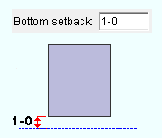
Bottom setback: The vertical distance (in the primary dimension " Units " or other units ) from the bottom of the tilt-up panel to the elevation to which the panel's concrete material is "set back" from the bottom of the panel. The elevation of the bottom of the panel is the elevation of its member line .
|
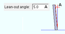
Lean-out angle: Zero , or a positive or negative (-) angle from 89 to -89 degrees. Changing this angle changes neither the " Height " nor the vertical distance from the bottom to the top of the panel. An entry of ' 0 ' results in a panel that does not lean.
|
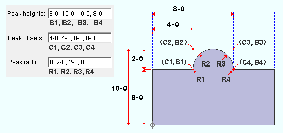
Peak heights: Blank , or a comma-delimited list containing at least one distance (in the primary dimension " Units " or other units ). Distances entered into this field are absolute; that is, they are not added or subtracted from the " Height ." Heights must correspond to distances entered in the " Peak offsets " field; distances lacking a corresponding entry are ignored.
" Peak heights ", " Peak offsets , and " Peak radii " options can be combined to add a profile to the top of a tilt-up panel.
|
|||
| Note the correspondence of height, offset, and radii entries. Each distance has a corresponding entry in the other two fields. |
Peak offsets: Blank , or a comma-delimited list containing at least one distance (in the primary dimension " Units " or other units ) by which an entry to the " Peak heights " field is offset from the tilt-up panel's left end. Distances entered to this field must correspond to those entered in the " Peak heights " field; distances lacking a corresponding entry are ignored.
Peak radii: Blank , or a comma-delimited list containing at least one distance (in the primary dimension " Units " or other units ). If the " Peak offsets " field contains a list of dimensions, this field will be populated with a list containing the same number of dimensions.
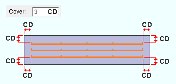
Cover: The distance (in the primary dimension " Units " or other units ) from the end of the rebar to each end of the tilt-up panel, and the minimum distance from the rebar to face of the panel. This applies when a Tilt-up Panel Reinforcement custom component has been applied to the panel.
|
concrete | F2 > concrete / rebar > | tilt-up panel | top
| Left/Right end settings |
------  Members ------
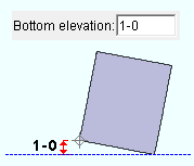
Bottom elevation: The vertical distance (in the primary dimension " Units " or other units ) from the end of the tilt-up panel to the bottom of the tilt-up panel. Unlike the setting for the " Bottom setback ," this affects the location of the member line.
|
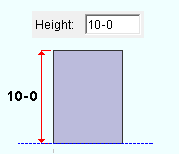
Height: The vertical distance (in the primary dimension " Units " or other units ) from the bottom of the tilt-up panel to the top of the panel. Changing the " Lean-out angle " does not change this vertical distance. Also, peaks may be added in addition to the distance entered for the " Height ."
|
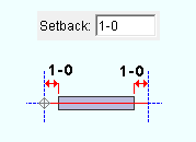
Setback: The horizontal distance (in the primary dimension " Units " or other units ) from the end of the tilt-up panel member end to the place to which the panel's concrete material is "set back" from the bottom of the panel.
|
|||
| In this example, a setback distance is entered for both the left and right ends of the panel. |
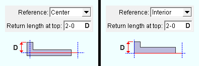
Return length at top: A distance (in the primary dimension " Units " or other units ). This applies when the " Return angle " field at the end for which you specify a return length contains a valid entry.
When an entry is made to this field, the " Return length at bottom " field is automatically populated with same value unless a user-entered value replaces it.
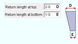
The top and bottom lengths of a return can differ. At any end, if at least one return length value is ' 0 ' , no return will be generated.
Return length at bottom : A distance (in the primary dimension " Units " or other units ). This applies when the " Return angle " field at the end for which you specify a return length contains a valid entry.
When an entry is made to the " Return length at top " field, the "Return length at bottom" field is automatically populated with same value unless a user-entered value replaces it.
At any end, if at least one return length value is ' 0 ' , no return will be generated.
|
|||
| The return length is measured from the member line .
As a result, if the panel's reference is ' Center ' , the return will measure longer than the return length entry. |
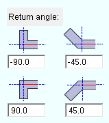
Return angle : A positive or negative (-) number of degrees. An entry of ' 0 ' is ignored. Depending on the thickness of the wall, some larger values may cause the concrete material to clash.
|
A ' positive number ' of degrees rotates the return counterclockwise that number of degrees from the axis of the panel's member line.
A ' negative number ' of degrees rotates the return clockwise that number of degrees from the axis of the panel's member line.
Miter angle : Zero , or a positive or negative (-) angle from 89 to -89 degrees. A non-zero entry applies a miter to the tilt-up panel end.
|
If the angle is ' 0 ', no miter will be applied to the end of the panel.
A ' positive number ' of degrees rotates the return counterclockwise that number of degrees from the position that is perpendicular to the axis of the panel's member line, or perpendicular to the return if a non-zero " Return length " is entered.
A ' negative number ' of degrees rotates the return clockwise that number of degrees from the position that is perpendicular to the axis of the panel's member line, or perpendicular to the return if a non-zero " Return length " is entered.
concrete | F2 > concrete / rebar > | tilt-up panel | top
