 Add Panel-to-Footing Embed Assembly ( Modeling )
Tool summary :

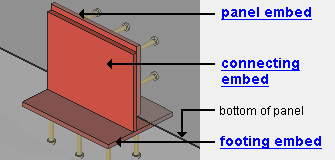
Panel-to-footing embed assemblies can consist of plates, channels, or angles. Here, an embed made entirely of plates is shown.
Also see :
| YouTube video: Adding Panel-to-Footing Embed Assemblies |
- Add Embed Assembly (a similar tool)
- Add Panel-to-Panel Embed Assembly (a similar tool)
- Embed Plate (plate embeds)
- Embed (angle or channel embeds)
concrete | the concrete command group in modeling
 To add a panel-to-footing embed assembly :
1 . Before using this tool, add to the Embed Schedule any plates, angles, or channels that you want to use in the to-be-added embed assembly.
3 . In Modeling , use Snap to Surface or a related tool to go to an elevation view that is parallel with a surface of the tilt-up panel that you will add the embed assembly to.
4 . Invoke Add Panel-to-Footing Embed Assembly . Its icon can be added to your toolbar (classic) or ribbon (lightning). The icon, keyboard shortcut or context menu command can be found in the group named ' Concrete '. For lightning, Customize Interface is used to configure ribbons, keyboards, the context menu, and modes.
5 . The status line prompts, " Locate Tilt-Up Panel ." Select the tilt-up panel that you want to add an assembly to.
5 . Locate- Pan -Return mouse bindings become active. The status line prompts, " Locate reference point. " The point locators On Polygon Line and ANNO becomes active. The point location target ( ![]() ) appears near the edge of the panel that your mouse pointer (
) appears near the edge of the panel that your mouse pointer (  ) is closest to, and moves with it. A dimension annotation indicates the distance that you have moved from the edge. When you are satisfied with that distance, left-click ( Locate ) to place a reference point. The reference point that you locate will lie at the midpoint of the to-be-added assembly along its length. It also lies along the bottom of the tilt-up panel.


bindings
6 . The Panel-to-Footing Embed Assembly window opens, do at least one of the following:
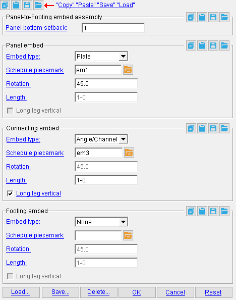
6a (optional) . Enter a " Panel bottom setback " to match the distance between the bottom of the tilt-up panel and its footing.
6a (optional). " Load " previously saved panel-to-footing embed assemblies.
7 . With the Panel-to-Footing Embed Assembly window still open, choose an " Embed type " and enter other options for the panel, connecting, and footing embeds. If you performed step 6b, you can edit the embed assembly that you loaded.
8 (optional) . " Save " the panel-to-footing embed assembly that you edited, if you want add it to other tilt-up panels.
9 . Press " OK " to close the Pad-to-Footing Embed Assembly window.
10 (optional) . The status line prompts, " Locate reference point. " Locate-Pan-Return mouse bindings become active. Left-click to place another embed assembly that is identical to the one that you edited in steps 6 - 9. Repeat this step as required.
11 . Right-click to exit the Add Panel-to-Footing Embed Assembly tool.
12 . If User and Site Options > Modeling > " Automatically process after modeling operation " is set to ' Process and create solids ', the panel-to-footing embed assembly will be generated immediately. If not, the embed will be generated in the tilt-up panel the next time the member undergoes Process and Create Solids .
concrete | the concrete command group in modeling
------ Panel-to-Footing embed assembly ------
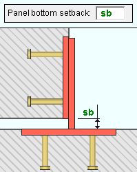
Panel bottom setback: A distance (in the primary dimension " Units " or other units ) by which the connecting and the footing embeds are set back -- lowered -- from the bottom of the panel embed. A positive distance lowers the connecting and the footing embeds relative to the bottom of the tilt-up panel. Therefore, a setting a positive distance can adjust the connecting and footing embeds by the thickness of shims between the panel and the footing.

|
A section view showing the " Panel bottom setback " between the bottom of a tilt-up panel and a concrete footing. The setback distance shown here is also the distance that the panel is shimmed above the footing. |
concrete | the concrete command group in modeling | top
------ Panel embed------
------ Connecting embed ------
------ Footing embed ------
Embed type: None or Plate or Angle/Channel .
' None ' prevents an embed from being generated when the embed assembly is added to the tilt-up panel.
' Plate ' adds an embed plate to the embed assembly. If a " Schedule piecemark " is chosen from the Embed Schedule , the embed will match that plate's entry in the schedule.
' Angle/Channel ' adds an embed angle or channel to the embed assembly. If a " Schedule piecemark " is chosen from the Embed Schedule , the embed will match that angle or channel's entry in the schedule.
Schedule piecemark: A standard submaterial mark from the Embed Schedule that you want applied to this part of the embed. This applies if the " Embed type " is not ' None '. Otherwise, this field will be disabled ( grayed out ).
To make an entry, you can type in the submaterial mark that you want (if you know it), or you can press the "file cabinet" browse button (
) and double-click any embed that is on the representation of the Embed Schedule that appears on screen. You can choose from either plates or angles and channels, depending on the choice you made to " Embed type ."
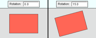
Rotation: A positive or negative (-) number of degrees by which the plate is rotated counterclockwise. When the plate is part of a panel or connecting embed, this is the angle when viewed toward the face of the tilt-up panel that the embed assembly is applied to. When it is part of a footing embed, this is the angle when viewed from the top of the footing looking down. A negative (-) entry rotates the plate clockwise. This applies if the " Embed type " is ' Plate '. Otherwise, this field will be disabled ( grayed out ).

|
An elevation view of rotated plates. |
Length: The length (in the primary dimension " Units " or other units ) of the angle or channel. This applies if the " Embed type " is ' Angle/Channel '. Otherwise, this field will be disabled ( grayed out ).
Long leg vertical: ![]() or
or ![]() . This applies if the " Embed type " is ' Angle/Channel '. Otherwise, this field will be disabled ( grayed out ).
. This applies if the " Embed type " is ' Angle/Channel '. Otherwise, this field will be disabled ( grayed out ).
If this box is checked (
), the long leg of the angle is aligned with the embed.
If the box is not checked (
), the long leg of the angle extends perpendicularly from the embed.
concrete | the concrete command group in modeling | top
To manage panel-to-panel embed assemblies :


"Load ..." opens the Select Assembly to Load window, from which you can select previously saved panel-to-footing embed assemblies and add them to tilt-up panels.
"Save ..." opens the Save As... window, in which you can enter a name and press ' OK ' to save the embed assembly for later use. Then, you can " Load... " the embed assembly with this tool or with the Add Embed Assembly tool.
"Delete ..." removes the embed assembly from the Select Assembly to Load window.
concrete | the concrete command group in modeling | top
To close the Add Panel-to-Panel Embed Assembly widow :


"OK" closes this window and completes the edit operation.
"Cancel" (or the Esc key or the
button) closes this window without saving changes you have made.
"Reset ..." undoes all changes made to this window since you first opened it. The window remains open.


