 Add Embed Assembly ( Modeling )
Tool summary :
Also see :
- Import Model (to import an IFC file)
- Add Panel-to-Panel Embed Assembly (a similar tool)
- Add Panel-to-Footing Embed Assembly (a similar tool)
- Embed Plate (plate embeds)
- Embed (angle or channel embeds)
concrete | the concrete command group in modeling
 To add an embed assembly :
1 . Before using this tool, add to the Embed Schedule any plates, angles, or channels that you want to use in the to-be-added embed assembly.
2 . In Modeling , use Snap to Surface or a related tool to go to an elevation view that is parallel with a surface of the tilt-up panel that you will add the embed assembly to.
3 . Place construction lines so that there is an INCL that lies at the midpoint of the to-be-added assembly along its length (before any " In-position rotation " is applied).
4 . Invoke Add Embed Assembly . Its icon can be added to your toolbar (classic) or ribbon (lightning). The icon, keyboard shortcut or context menu command can be found in the group named ' Concrete '. For lightning, Customize Interface is used to configure ribbons, keyboards, the context menu, and modes.
5 . The status line prompts, " Locate reference point. " Locate- Pan -Return mouse bindings become active. Left-click ( Locate ) to place a reference point for the embed assembly at the INCL that you added in step 3. The reference point that you locate will lie at the midpoint of the to-be-added assembly along its length.


bindings
6 . The status line prompts, " Locate lengthwise direction. " Locate-Pan-Return mouse bindings remain active. The direction of the line between the reference point you located previously and the point you select will indicate the direction of the length of the assembly.
7 . The status line prompts, " Locate near-side direction. " Locate-Pan-Return mouse bindings remain active. The direction of the line between the reference point you located previously and the point you select will indicate the near side of the assembly. If, in step 9, you enter ' 0 ' as the " Angle " of a plate, angle, or channel member that you " Add ", and choose ' Near side ' for " On assembly side ," the width of the member will be placed on the near side of the assembly's reference point.
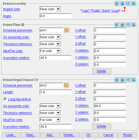
8 . The Embed Assembly window opens. You must do at least one of the following:
8a (optional). " Load " previously saved embed assemblies and add them to the embed assembly that you are editing here, on this window.
8b (optional). " Add " embed plate, angle, or channel members to the embed assembly that you are editing.
9 . Choose an " Angled side " and enter an " Angle " for the assembly, choose a " Schedule piecemark ," and other options for the embed members, then press " OK " to close the Embed Assembly window.
10 (optional) . The status line prompts, " Locate next assembly reference point. " Locate-Pan-Return mouse bindings become active. Left-click to place another embed assembly that is identical to the one that you edited in steps 8 and 9. Repeat this step as required.
11 . Right-click to exit the Add Embed Assembly tool.
12 . If User and Site Options > Modeling > " Automatically process after modeling operation " is set to ' Process and create solids ', the embed assembly will be generated immediately. If not, the embed will be generated in the tilt-up panel the next time the member undergoes Process and Create Solids .
concrete | the concrete command group in modeling
------ Embed assembly ------
Angled side: Near side or Far side .
' Near side ' rotates the near side of the embed assembly out of the screen by the " Angle " along its length.
' Far side ' rotates far side of the embed assembly out of the screen by the " Angle ."
Angle: A positive or negative (-) number of degrees that the embed assembly is rotated along its length into or out of the screen. If the angle is ' 0 ', no rotation takes place.
------ Embed Plate ------
------ Embed Angle/Channel------
Schedule piecemark: A standard submaterial mark of a member from the Embed Schedule for part of the embed assembly. You must make a valid entry, or you will not be able to close this window using " OK ."
To make an entry, you can type in the submaterial mark that you want (if you know it), or you can press the "file cabinet" browse button (
) and double-click an embed that is on the representation of the Embed Schedule that appears on screen. You can choose from either plates or angles and channels, depending on whether this option is in an Embed Plate or Embed Angle/Channel section.
Length: The length (in the primary dimension " Units " or other units ) of the angle or channel. This option applies only to an Embed Angle/Channel section.
Long leg vertical: ![]() or
or ![]() . This option applies only to an Embed Angle/Channel section.
. This option applies only to an Embed Angle/Channel section.
If this box is checked (
), the long leg of the angle extends perpendicularly from angle or channel when the " Angle " of the assembly is also ' 0 '.
If the box is not checked (
), the long leg of the angle is aligned with the member when the " Angle " of the assembly is also ' 0 '
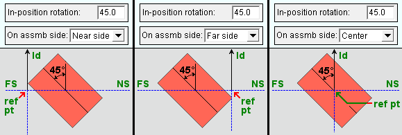
On assembly side: Near side or Far side or Center .

|
When the " Angle " of the assembly is ' 0 '...
' Near side ' places the member to the near side of the assembly's reference point.
' Far side ' places the member to the far side of the assembly's reference point.
' Center ' centers the member on the assembly's reference point.
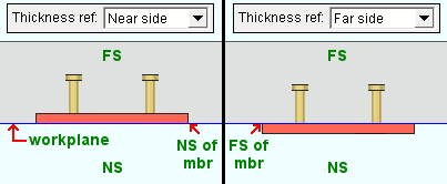
Thickness reference: Near side or Far side .
|
When the " Angle " of the assembly is ' 0 '...
' Near side ' places the near side of the member coplanar to the work plane of the view in which you placed the embed. The member's thickness is perpendicular into that view, away from you.
' Far side ' places the far side of the member coplanar to the work plane of the view in which you placed the embed. The member's thickness is perpendicular out of that view, towards you.
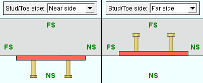
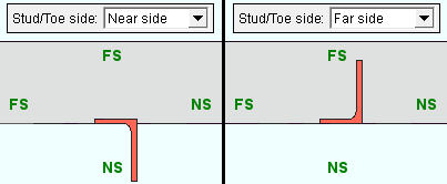
Stud/Toe side: Near side or Far side .
|
A plan view of two plates with different " Stud/Toe " settings. (Embed assemblies are added in an elevation view.) |
|
A plan view of two angles with different " Stud/Toe " settings. |
When the " Angle " of the assembly is ' 0 '...
' Near side ' positions the member so that, when viewed from work plane of the view in which you placed the embed assembly, a stud (if a plate with studs) or toe (if an angle) protrudes out of the view, toward you.
' Far side ' positions the member so that a stud (if a plate with studs) or toe (if an angle) protrudes into the view, away from you.
In-position rotation: A positive or negative (-) number of degrees by which the plate, angle, or channel is rotated from its length through the embed assembly's reference point. When viewed from work plane of the view in which you placed the embed assembly, the member is rotated counterclockwise from the lengthwise direction.
|
| ld = the lengthwise direction that you indicated when you placed the embed assembly. |
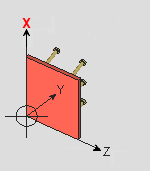
X offset: The distance (in the primary dimension " Units " or other units ) of the plate, angle, or channel from the embed assembly's insertion point along the lengthwise direction that you located.
|
When the " Angle " of the assembly is ' 0 ' and it is otherwise unrotated, a positive offset positions the member along its length. |
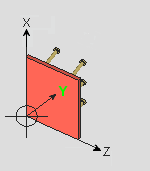
Y offset: A distance (in the primary dimension " Units " or other units ) from the plate, angle, or channel's insertion point into or out of the work plane.
|
When the " Angle " of the assembly is ' 0 ', when the lengthwise direction is up, and when the near side is to your right of the length in the work view, a positive distance offsets the member into the screen. |
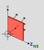
Z offset: A distance (in the primary dimension " Units " or other units ) from the reference point perpendicular to the length of the plate, angle, or channel toward its near side.
|
When the " Angle " of the assembly is ' 0 ', a positive distance offsets the member in the direction of the near side when viewed in the work plane. |
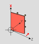
X rotation: A positive or negative (-) number of degrees that the member is rotated in the view along the lengthwise direction that you located.
|
When the " Angle " of the assembly is ' 0 ', the axis of rotation is along its length and through its reference point. |
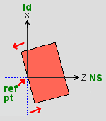
Y rotation: A positive or negative (-) number of degrees that the member is rotated in the view.
|
When the " Angle " of the assembly is ' 0 ', when the length points up, and when the near side is to the right in the view, the member rotates counterclockwise around its reference point.
ld = lengthwise direction |
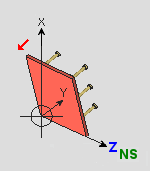
Z rotation: A positive or negative (-) number of degrees that the member is rotated in the view.
|
When the " Angle " of the assembly is ' 0 ', the axis of rotation is perpendicular to the embed assembly's length and through its reference point. |
![]() removes an Embed Plate or Embed Angle/Channel section, and thus a plate, angle, or channel member, from the embed assembly you are editing.
removes an Embed Plate or Embed Angle/Channel section, and thus a plate, angle, or channel member, from the embed assembly you are editing.
To manage embed assemblies :


"Load ..." opens the Select Assembly to Load window, from which you can select previously saved embed assemblies and add them to tilt-up panels.
"Save ..." opens the Save As... window, in which you can enter a name and press ' OK ' to save the embed assembly for later use. Then, you can " Load... " the embed assembly with this tool.
"Add..." opens a Select Member Type window, from which you can select either an " Embed Angle/Channel " or an " Embed Plate ."
"Delete ..." removes the embed assembly from the " Select Assembly to Load " window.
concrete | the concrete command group in modeling | top
To close the Embed Assembly widow :


"OK" closes this window and completes the edit operation.
"Cancel" (or the Esc key or the
button) closes this window without saving changes you have made.
"Reset ..." undoes all changes made to this window since you first opened it. The window remains open.


