 Add Tilt-up Panel Reinforcement ( Modeling )
Tool summary :
- Reinforces a tilt-up panel with rebar mats.
Also see :
- Modeling (where custom components can be added)
- Concrete Reinforcement Defaults ( Concrete Job Setup window, sets defaults for this window)
- Custom components (topic)
- Component Plugin Setup ( Home > Project Settings > Job > Plugin Defaults >)
- Copy Component (to copy the component to another tilt-up panel)
- Move Component (to move the component to another tilt-up panel)
- Explode Component (makes the component no longer a component)
- Component Selection Tool (to search for custom components of a selected type)
- Model Tree (to find custom components and select them for deletion, editing, etc.)
concrete | model > component > | add component | top
 To add, edit or delete the Tilt-Up Panel Reinforcement :
Setup of default settings is available for the edit window that opens when you add this component. See Home > Project Settings > Job > Plugin Defaults > Component Plugin Defaults .
To add the custom component: 1 ) Set your Selection filter " to ' Members ' and select the panel to which you want to add the reinforcement. 2 ) In Modeling , choose Model > Component > Add . 3 ) On the custom component selection list, choose " Tilt-Up Panel Reinforcement " as the custom component you want to add. 4 ) The Tilt-Up Panel Reinforcement Edit window opens. Check at least one mat (e.g. " Center mat ") as desired. Press " OK " to close the window. 5 ) If User and Site Options > Modeling > " Automatically process after modeling operation " is set to ' Process and create solids ', the rebar is generated immediately. If not, the reinforcement will be generated on the panel the next time it undergoes Process and Create Solids .
Tip: If you use in-tool selection -- that is, select the panel after selecting " Tilt-Up Panel Reinforcement " as the custom component you want to add -- only tilt-up panels will be selectable. Also, it will not be necessary to set your Selection filter " to ' Members '. To delete a Tilt-Up Panel Reinforcement custom component: 1 ) Use the Component Selection Tool and select the component on the tilt-up panel. Or , select the component in the Model Tree . It will be listed under its under its tilt-up panel member and not under the group member to which the panel belongs 2 ) Press the (or choose Edit > Delete ). 3 ) Process and Create Solids , if User and Site Options > Modeling > " Automatically process after modeling operation " is not set to a choicet that automatically creates solids.
To edit a Tilt-Up Panel Reinforcement component using a member edit window, you can open the Tilt-up Panel Edit window of the member on which the reinforcement is placed. Select the tilt-up panel, right-click and choose Edit Other , then choose the tilt-up panel member. The component's settings will be contained in that window in a section named [ Reinforcement ].
You can edit a Tilt-Up Panel Reinforcement custom component without opening the Tilt-up Panel Edit window. Set the " Selection filter " to ' Custom Components ''. Select a material of the reinforcement, right-click, and choose Edit . Or, select the component by double-clicking it.
To multi-edit all of the Tilt-Up Panel Reinforcement custom components, use the Component Selection Tool to select that component type
You can also edit a Tilt-Up Panel Reinforcement component using the Model Tree . In the Model Tree , the custom component is listed as Tilt-Up Panel Reinforcement when " View By " is set to ' Member piecemark ' or ' Member number '. The Tilt-Up Panel Reinforcement component is listed under its panel, after that member's connection components ( Left End and Right End ), and before that member's submaterials. It is not listed under the group member to which the panel belongs.
concrete | model > component > | add component | top
 Tilt-up Panel Reinforcement custom component settings :
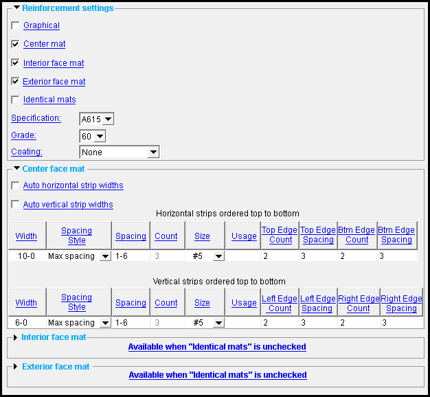
------  Reinforcement settings ------
|
A Tilt-up Panel Reinforcement component is automatically set to "
Graphical " whenever you make graphical changes to any of its rebar. For example, when you Edit Material or apply the Extend Rebar Ends tool to rebar. This stops the component from being changed during Process and Create Solids . Click here for more information.
Instead of allowing the component to be made "
Graphical ," you may wish to Explode Component .
If this box is checked (
), the reinforcement will include a center mat.
If the box is not checked (
), the reinforcement will not include a center mat.
If "
Identical mats " and "
Interior face mat " or the "
Exterior face mat " option turned on (checked), the
Center face mat table settings also apply to the interior or exterior face mats. This is true even if "
Center mat " is not turned on (checked).
If this box is checked (
), the reinforcement will include an interior face mat.
If the box is not checked (
), the reinforcement will not include an interior face mat.
If "
Identical mats " is also turned on (checked), the
Center face mat table settings also apply to the interior face mat. This is true even if "
Center mat " is not turned on (checked). Whether a face of the tilt-up panel is considered interior or exterior depends on where the points were added when it was placed.
If this box is checked (
), the reinforcement will include an exterior face mat.
If the box is not checked (
), the reinforcement will not include an exterior face mat.
If "
Identical mats " is also turned on (checked), the
Center face mat table settings also apply to the exterior face mat. This is true even if "
Center mat " is not turned on (checked). Whether a face of the tilt-up panel is considered interior or exterior depends on where the points were added when it was placed.
If this box is checked (
) and either of the boxes for " Interior face mat " and " Exterior face mat " are checked, the settings for interior and exterior face mats are identical to those from the
Center face mat tables..
If the box is not checked (
), the interior or exterior face mats get unique settings from the
Interior face mat or
Exterior face mat tables.
Specification: A615 or A706 or etc. This is an ASTM specification entered into the Rebar Specifications window.
Grade: 60 or 40 or etc. This is the yield strength (grade) of the rebar.
The grade choices in this list box are limited to those entered in the Rebar Specification window for the " Specification " chosen for this rebar.
Coating: None or a Coating designation that is available in the " Standard " that you have selected.
The coating choices in this list box are limited to those entered in the Rebar Specification window for the " Specification " chosen for this rebar shape.
Select ' None ' if you do not want a coating. Since it is possible to create specifications that do not have coatings, it is possible that ' None ' may be your only option.
User configuration: If a coating is not available for selection, selecting a different " Specification " will make that coating available if the coating you want is in that other standard. If you don't want to change to a different " Specification ," you can open the Rebar Specifications window and add the coating you want to the specification that you currently have selected.
------  Center face mat ------
Auto horizontal strip widths: ![]() or
or ![]() .
.
If this box is checked (
), any distance entered into the " Width " field in the Horizontal strips... table will be reset to the auto width value after your select " OK " to close the Tilt-up Panel Reinforcement edit window.
If the box is not checked (
), any distance you enter into the " Width " field that is less than or equal to the auto width value will be the vertical distance within which horizontal strips will placed, measured from the top of the tilt-up panel.
Auto vertical strip widths: ![]() or
or ![]() .
.
If this box is checked (
), any distance entered into the " Width " field in the Vertical strips... table will be reset to the auto width value after your select " OK " to close the Tilt-up Panel Reinforcement edit window.
If the box is not checked (
), any distance you enter into the " Width " field that is less than or equal to the auto width value will be the horizontal distance within which vertical strips will placed, measured from the left end of the tilt-up panel.
Width: A distance (in the primary dimension " Units " or other units ). This will be the length of the rebar, plus the cover distance between the two ends.
Depending on whether the field is in the Horizontal strips... or Vertical strips... table, if " Auto horizontal strip widths " or " Auto vertical strip widths " is not checked (
), any distance entered into this field will be reset to the auto width value after you select " OK " to close the Tilt-up Panel Reinforcement edit window.
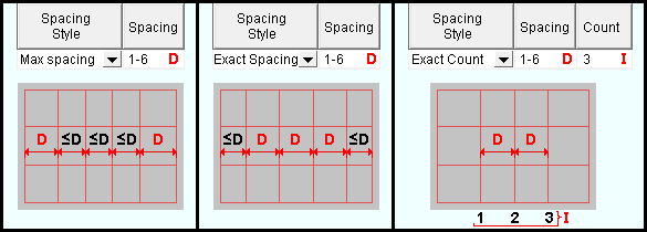
Spacing Style: Max spacing or Exact spacing or Exact count .
|
| The " Spacing " value is applied differently when a different " Spacing Style " is chosen. |
Spacing: A distance (in the primary dimension " Units " or other units ). This is the distance on center (o.c.) by which the strips are spaced, given the constraints introduced by the " Spacing Style " and (when applicable) the " Count ".
Count: A positive integer . This sets the number of rebar when " Spacing Style " is set to ' Exact count '. Otherwise, this option is disabled ( grayed out ). If the " Count " distance multiplied by the " Spacing " distance exceeds the " Width ", the spacing distance takes precedence and the count is ignored.
Size: A size designation that has been entered to the Rebar Definitions Setup window under the " Active rebar standard ".
Usage: Blank or any string . A manually entered description similar to those found in the Rebar Usage Descriptions window is appropriate here.
Top Edge Count: A positive integer . An example of tilt-up panel reinforcement with multiple top edge rebar is shown below.

|
These top edge count options design 2 top edge rebars spaced 3" o.c. |
Top Edge Spacing: A distance (in the primary dimension " Units " or other units ). An example of tilt-up panel reinforcement with multiple top edge rebar is shown above.
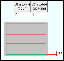
Bottom Edge Count: A positive integer . An example of tilt-up panel reinforcement with multiple bottom edge rebar is shown below
|
These bottom edge count options design 2 bottom edge rebars spaced 3" o.c. |
Bottom Edge Spacing: A distance (in the primary dimension " Units " or other units ). An example of tilt-up panel reinforcement with multiple bottom edge rebar is shown above.
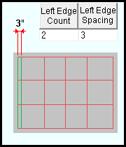
Left Edge Count: A positive integer . An example of tilt-up panel reinforcement with multiple left edge rebar is shown below
|
These left edge options design 2 left edge rebars spaced 3" o.c. |
The location of the left edge depends upon the order in which the tilt-up panel's workpoints were entered.
Left Edge Spacing: A distance (in the primary dimension " Units " or other units ). An example of tilt-up panel reinforcement with multiple left edge rebar is shown above.
Right Edge Count: A positive integer . An example of tilt-up panel reinforcement with multiple right edge rebar is shown below
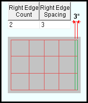
|
These right edge options design in 2 right edge rebars spaced 3" o.c. |
The location of the right edge depends upon the order in which the tilt-up panel's workpoints were entered.
Right Edge Spacing: A distance (in the primary dimension " Units " or other units ). An example of tilt-up panel reinforcement with multiple right edge rebar is shown above.
------  Interior/Exterior face mat ------
The options in this table are identical to those in the table in the " ![]() Center face mat" leaf.
Center face mat" leaf.
