"  Web Plate " & "
  Web Fill Plate " connection design locks
| Connection design of a beam-to-beam splice plate connection is done per " |
|
||||
"  |
"  |
|||
|
||||
End connection failure message: Beams have unequal plan rotations .
Connection Guide: Click here , here , here or here .
User Defined Connections: Settings that are locked (
) in a user defined connection file will automatically be locked on a member edit window for which that file is the " Input connection type ." You can, if you so choose, manually lock additional settings on the member edit window, and your changes will be retained, through multiple processes, so long as you do not change to a different connection then switch back to the original user defined connection.
Beam Edit: To change a setting, first set it to locked (
). Related settings that are unlocked (
) may be updated, and the "
Left/Right end limit state " calculations will be updated. Settings that are locked (
) will not be changed by connection design , even if doing so might prevent a connection failure.
Connection design locks :
| Locks not dimensioned or called out on the drawings are marked ( not depicted ). |
![]() Web Plate
Web Plate
Web plates, NS and FS
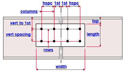
Top of plate ( top ): The distance (perpendicular to the work lines of the beams) from the top flange of the beam to the top of either of the splice plates. The example shows the near side splice plate. If the beams being spliced are non-sloping, the " Top of plate " dimension is vertical. Changing " Top of plate " repositions the plates, but does not move the holes on the plates. To move the holes, change the " Vertical to 1st hole " distance.
Plate length ( length ): The distance (parallel with the depth of the beams) between the two edges of the splice plate that are parallel with the work lines of the beams (see example ). If the beams that are being spliced are non-sloping, then " Plate length " dimension is vertical. If " Plate length " is unlocked (
), changing the " Vertical hole spacing " or number of " Rows " also changes the " Plate length ." The " Plate length " also sets the fill plate length.
Plate width ( width ): The distance (parallel with the work lines of the beams) between the two edges of the splice plate that are parallel with the depth of the beams (see example ). If the beams being spliced are non-sloping, the " Plate width " dimension is horizontal. If " Plate width " is unlocked (
), changing " Horizontal to 1st hole " or " Horizontal hole spacing " or the number of " Columns " also changes the " Plate width ."
Plate thickness ( not depicted ): The " Material thickness " of either splice plate. This distance applies to both the near side and far side splice plates.
Relative rotation ( not depicted ): The number of degrees relative to the orientation of the supported beam that the splice plate is to be rotated. A " Relative rotation " of ' 0 ' aligns the top of the splice plate parallel with the top flange of the beam. If you lock (
) this field and enter a value other than the value that connection design enters automatically, you will get the connection failure message " Design of rotated connections is not supported ."
Design of rotated connections is not supported Unlocking (
) the " Relative rotation " causes the end connection failure message to go away. It also causes connection design to repopulate the field with an acceptable value.
If you want to apply the locked value that produces this failure message, you need to "
Force " the connection. A solids model will be created, but the Connection Design Calculations report (and Expanded Connection Design Calculations ) will include a warning that connection capacity calculations require engineering review since, as the message states, rotated connections are not supported.
Bolts on web plates
Bolt diameter ( not depicted ): You can either type in any diameter (inches or mm) or select a bolt diameter from the combo box (
). The diameters that are listed in the combo box come from Home > Project Settings > Job > Bolt Settings > the " Available bolt diameters " list. The bolt diameter entered here together with the " Hole type " set the diameter of holes the bolts go into.
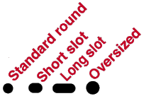
Hole type ( not depicted ): Standard round or Short slot or Oversized or Long slot or User slot #1 or User slot #2 . The hole type selected here, together with the " Bolt diameter " entered above, set the diameter of holes for bolts to the beam web.

Rows: The number of rows of holes. Row spacing runs perpendicular to the work lines of the beams -- see the example . If " Plate length " is unlocked (
), changing the number of " Rows " also changes the " Plate length ."
Vertical to 1st hole ( vert to 1st ): The distance (perpendicular to the work lines of the beams) from the top flange of the beam to the nearest row of holes (see example ). If the beams being spliced are non-sloping, then the " Vertical to 1st hole " dimension is vertical.
Vertical hole spacing ( vert spacing ): The distance (center to center) between any two adjacent rows of holes. Bolt row spacing runs perpendicular to the work lines of the beams (see example ). If the beams being spliced are non-sloping, then the " Vertical hole spacing " dimension is vertical. If " Plate length " is unlocked (
), changing the " Vertical hole spacing " also changes the " Plate length ."
Columns: Half the total number of columns of holes on a splice plate. Hole column spacing runs parallel with the work lines of the beams. In other words, this is the number of columns of holes on half of the splice plate. In the example above, this number is ' 2 '. If " Plate width " is unlocked (
), changing the number of " Columns " also changes the " Plate width ."
Horizontal to 1st hole ( 1st ): The distance (parallel with the work lines of the beams) from the connection center line (half way between the two beams) to the nearest column of holes (see example ). If " Plate width " is unlocked (
), changing the " Horizontal to 1st hole " also changes the " Plate width ."
Horizontal hole spacing ( hspc ): The distance between any two adjacent columns of holes on the same beam (see example ). If " Plate width " is unlocked (
), changing the " Horizontal hole spacing " also changes the " Plate width ."
| Note: Connection design will automatically design NS and FS web fill plates for beam splice connections to compensate for web thickness differences between the two beams. If the two beams have equally thick webs, a " |
Web fill plates, NS and FS
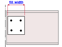
Plate width ( fill width ): The distance (parallel with the work lines of the beams) between the two edges of the fill plate that are parallel with the depth of the beams. Two fill plates are designed along with the two splice plates if fill plates are required to make up the difference between the web thicknesses of the two beams.
Fill plate thickness ( not depicted ): The " Material thickness " of the fill plate. This same thickness applies to both the near side and far side fill plates. Two fill plates are designed with the two splice plates if fill plates are required to make up the difference between the web thicknesses of the two beams.
Other fill plate dimensions are controlled by the " Web Plate " locks: The " Plate length " of the web plate sets the fill plate length. The hole pattern in the web plate sets the hole pattern in the fill plate.


