Beam End Connection Failure Messages
Messages in alphabetical order:
| A | B | C | D | E | F | H | I | L | M |
| N | O | P | R | S | T | U | V | W |
Where/when/why these error messages appear:
When you open a Beam Edit window after connection design has failed an Input connection type connection on the left or right end of the beam, you will find a connection design error message such the following:
| Beam web shear strength failed |
The message is displayed on the left half of the Beam Edit window if it applies to the connection on the left end of the beam. The message tells you why connection design failed the connection. Understanding the message can help you to determine what steps you need to take in order to create the connection you want.
Changing connection design locks or other settings on a Beam Edit window triggers Process within member edit. When adjusting member edit window settings to fix a connection, please heed the following warnings.
Warning 1: Loads should be entered (Tension load, Shear load, Moment load, Compression load, etc.) only under the authority of a qualified engineer. Lowering the load may get you a connection, but it could result in a connection failure under the true loading conditions in the built structure.
Warning 2: Design changes should be made (such as changing the Section size or Steel grade) only under the authority of a qualified structural designer. Making such design changes may involve extra cost, clearance problems, delays, etc. For many projects, materials may have already been ordered at the time connections are being designed.
Warning 3: Creating
Graphical connections or applying assemblies or parametrics are methods that users can always use to get around connection failures. Make sure that each graphical connection is approved by a qualified designer before its drawing is sent to the fabrication shop.
Warning 4: Fixing connection failures may, in some cases, involve making changes to Job/Fabricator Option files. Use great caution when you make such changes and always be prepared to later undo those changes. To apply such changes, a good procedure is to Mark for Processing any members that you want changed, then Process and Create Solids.
Warning 5: Just because connection design passes a connection without a failure message, you should not assume that the connection is optimal. All connections should be visually inspected in the model. In addition, the Connection Design Calculations or Expanded Connection Design Calculations report should be reviewed by a qualified engineer.
- A -
Allowable clip OSL bending strength exceeded: This end connection failure message indicates that the outstanding leg on the clip angle connection applied to this end of the beam is overstressed.
To fix this problem, you may want to use stronger materials (for example, use Heavy instead of Regular angle material). Or you may have to adjust the relevant Home > Project Settings > Fabricator > Standard Fabricator Connections > Clip angle configuration so that it uses a standard angle size with thicker legs.
Or you can lower the Tension load on the beam and thus allow the connection to be designed with the materials currently entered.
Before attempting to fix this connection, see the warnings.
Angle thickness less than recommended by AISC: This connection failure message applies to single-angle connections (Side = Near side or Far side). It can also apply when the Plate thickness for a ![]() Bent Plate
Bent Plate
Single-angle connections:
This applies when the Connection design method is ASD16 or LRFD16 or ASD15 or LRFD15 or ASD14 or LRFD14 or ASD13 or LRFD13 or ASD9 or LRFD3. Page 10-133 of the AISC 14th edition stipulates the following for single-angle connections:
Minimum Angle Thickness Bolt Diameter 3/8 inch (9.5 mm) 3/4 inch (28 mm) 7/8 inch (22 mm) 1/2 inch (12 mm) 1 inch or greater
(24 mm or greater)To fix this problem, you should enter a different Standard angle size for the offending bolt diameter specified in the Single Clip Angles Bolted OSL or All-Bolted, Single Angle or Single Clip Angles Welded OSL clip angle configuration.
At Home > Project Settings > Job > Design > Design Settings > Design Method, checking the box for
will allow single-angle connections to be designed using angles that are less than 3/8 inch thick. Double-angle connections:
This applies when the Connection design method is ASD16 or LRFD16 and the connection is axially loaded. A beam connection is considered axially loaded when the beam member's Tension load and/or Compression load have a value greater than 0, or possibly when Add gusset-beam interface forces to beam is
To fix this problem:
- Change the clip angle's section size directly on the beam edit window.
- Change the Standard angle size for the applicable bolt diameter specified in the Heavy Gage OSL All-Bolted Clip Angles or Wide Gage OSL All-Bolted Clip Angles or Narrow Gage OSL All-Bolted Clip Angles or Welded OSL Bolted/Welded Clip Angles or Heavy Gage OSL Bolted/Welded Clip Angles or Wide Gage OSL Bolted/Welded Clip Angles or Narrow Gage OSL Bolted/Welded Clip Angles or All-Welded Attached to Supporting Clip Angles or All-Welded Attached to Supported Clip Angles.
- At Home > Project Settings > Job > Design > Design Settings > Design method, check the box
Before attempting to fix this connection, see the warnings.
Axial load not applicable to this connection type: You can get this message when a Tension load or Compression load has been entered to the end of a beam that has one of the following connections:
| Beam connections that can't take axial loads. |
| A Seated connection. |
| A W Tee shear connection. |
| Single clip angles (Near side or Far side). |
| Double clip angles attached to the Supporting. |
| Any clip angle designed using Eurocode |
| Moment end plate splice connections. |
| Bent plate connections. |
| Non-moment beam splice connections. |
| HSS beam connections other than end plates. |
One way to get the originally selected Input connection type on this end of the beam is to enter zero (0) as the Tension load or Compression load.
Another way to get a system connection is to change the Input connection type and adjust the
Connection specifications.
Beam connections can take axial loads. Clip angles (double to the supported). End plates (except splices). Shear through plates. Built-up plates shear connections Single-plate shear connections. Before attempting to fix this connection, see the warnings.
- B -
Base metal failure of flange weld: This connection failure message applies to bolted moment flange plates, which may be designed, for example, when a wide flange beam frames to a wide flange column web or flange and the Input connection type is Shear or Clip angle and the Moment type is Bolted.
The message indicates that because the user has entered a too-small Plate thickness in the
To clear this failure message and get a connection, you could try increasing the Plate thickness, or you could
unlock the Plate thickness so that connection design is permitted to automatically calculate the required thickness.
Before attempting to fix this connection, see the warnings.
Beam connections cannot have 0.0 shear loads: You get this message when the beam's Shear load has been reduced to 0.
To try and get the original connection, try increasing the Shear load for that end to above 0.
Beam flange and web fails in compression: This end connection failure message applies when the Connection design method is EUROCODE 3 or EUROCODE 3 UK and the Input connection type connection is End plate and the Moment type is Bolted.
Beam flange interference with adjacent beam: You get this message when there is beam flange interference because two beams (with single-plate shear connections) are too close to one another on the same side of the web of a supporting beam.
A possible way to get the originally specified Input connection type connection in this situation is to try to Move... (or Move...) the end of one of the beams. Or you could delete one of the beams and add it again so that it is farther apart from the other beam. Or you could change the Section size on one or both of the beams. Or adjust the End preparation to get rid of the interference.
Before attempting to fix this connection, see the warnings.
Beam moment connections cannot have 0.0 moment loads: You get this message when the beam's Moment load has been reduced to 0.
To try and get the original connection, try increasing the Moment load for that end to above 0.
Beam net shear strength exceeded: This may apply to any type of connection, ![]() Moment or non-moment, that can be applied to the end of a beam. It indicates that the beam is overstressed due to net section shear stress.
Moment or non-moment, that can be applied to the end of a beam. It indicates that the beam is overstressed due to net section shear stress.
Possible ways to get the originally specified Input connection type connection include inputting a stronger beam Section size, changing the Steel grade to a steel with higher yield strength, or to lower the Shear load.
Before attempting to fix this connection, see the warnings.
Beam not deep enough for connection: This end connection failure message results when, because of the load on this end of the beam, the required connection depth for the clip angle, bent plate, shear plate, or splice connection exceeds the depth of the beam. You can also trigger this message by locking the Plate depth in the ![]() Bent Plate leaf or Plate width
Bent Plate leaf or Plate width ![]() Shear Tab leaf to a dimension that is near to or greater than the beam depth.
Shear Tab leaf to a dimension that is near to or greater than the beam depth.
One way to get a system connection that does not have to be so deep is to use larger diameter bolts. Making larger bolt diameters available for connection design to increment to may be done on the Bolt Settings window, under Available bolt diameters, for any of the aforementioned connection types. Or you can simply type in a larger NM bolt diameter on the Beam Edit window. Do not select a diameter from the
combo box for that field—since the choices on that combo box come from the Available bolt diameters list and it is likely that connection design has already tried those bolts—instead type in a diameter that will work. Also, be aware that the row spacing of shear tabs are adjusted per NM bolt diameter based on the Bolt spacings in Connection Detailing/Fabricator Options setup.
Another way to get connection design to generate a connection is to lower the Shear load and thus allow a weaker connection—with fewer rows of bolts—to be designed.
Or you can change the Section size so that the beam is deeper, thus allowing connection design to add another row of bolts to the beam web.
If the connection is a clip angle, you can choose If required for Extend past flange so that a web extension plate can be designed.
Before attempting to fix this connection, see the warnings.
Beam or conn. is above top of column: This applies to beam-to-column moment connections and indicates a problem in geometry where, if the connection had not failed, the beam or connection would extend above the column and thus present interference problems.
One way to better assess the problem is to review the 3D model to evaluate the framing situation. To fix the problem, you may be able to adjust the End elevation on the column or beam.
Before attempting to fix this connection, see the warnings.
Beam or conn. is below bottom of column: This applies to beam-to-column ![]() Moment connections and indicates a problem in geometry where, if the connection had not failed, the beam or connection would extend below the column and thus present interference problems.
Moment connections and indicates a problem in geometry where, if the connection had not failed, the beam or connection would extend below the column and thus present interference problems.
One way to better assess the problem is to review the 3D model to evaluate the framing situation. To fix the problem, you may be able to adjust the End elevation on the column or beam.
Before attempting to fix this connection, see the warnings.
Beams at splice must have same moment configuration: This applies to beam-to-beam moment splice plates when different AISC moment end plates are used, or when two different MBMA moment end plates are used, or when an AISC moment end plate is used on the one beam and a MBMA moment end plate is used on the opposing beam.
To fix this problem, edit the two beams that are being spliced, one beam at a time. Set the Moment type on the right end of the beam whose right end is being spliced so that it is the same as the Moment type on the left end of the opposing beam. Make the Bolt pattern the same for both connections.
Before attempting to fix this connection, see the warnings.
Beams have unequal plan rotations: This connection failure message applies to a beam-to-beam splice plate connection that has failed because the two beams being connected are not collinear.
To get the originally specified Input connection type connection, you have to reorient one or both of the beams. For instance, Erase one beam, then Add a new beam that is collinear with the other beam.
Otherwise you may have to create a
Before attempting to fix this connection, see the warnings.
Beams have unequal slopes: This applies to beam splice moment connections. SDS2 connection design does not create a beam splice moment connection when the beams have unequal slopes.
To fix this problem, you may be able to change the slope (End elevation) of one or both of the beams.
Or you could Erase one beam, then use EXPT to add a construction line along the workline of the remaining beam. Add the new beam so that its workline is along the construction line you just added. This ensures that the new beam is collinear with the other beam.
Before attempting to fix this connection, see the warnings.
Beam to beam moment conn must have a member opposite: This applies to both bolted and welded beam-to-beam moment connections. In either case, the supported beam must have a beam opposite to it to prevent twisting of the supporting beam.
To get connection design to create this connection, you need to add a new beam on the opposite side of the supporting beam's web. The new beam must be collinear with this beam (the beam this connection failure message is on).
Related failure messages: Moments at conn must be equal but opposite sign and Both beams at connection must have same moment type.
Before attempting to fix this connection, see the warnings.
Bearing strength on flg-pl/bm-flg exceeded: This failure message applies to bolted moment flange plates, which may be designed when a wide flange beam frames to a wide flange column web or flange and the Input connection type is Shear, Clip angle, or User defined and the Moment type is Bolted.
The message indicates that the total flange force (axial load + resolved component of moment) exceeds the bearing strength of either the flange plate or the beam flange.
Most likely you will get the Flange plate bolt shear strength exceeded failure message before you get this message. However, there may be conditions under which this connection failure message may be generated due to a distance entry to the
locked Rows (of bolts) field found in the
Assuming that the beam's Moment load and Tension load and Compression load are to engineering specifications, generally the best way to clear this failure message is to
Before attempting to fix this connection, see the warnings.
Beam web doubler bearing strength exceeded: Beam web doublers may be designed when the beam's Input connection type is Clip angle. Web doublers may automatically be designed, without a user having to lock any fields, for beam-to-beam framing conditions in order to compensate for a cope made to the supported beam's top flange. This failure occurs when a bolted web doubler's bearing strength is exceeded. You get bolted web doublers when the clip angle is bolted to the web of the supported beam.
The connection failure message may be generated when Plate thickness in the
Assuming that the beam's Shear load and Moment load is to engineering specifications and the doubler is already sized as you want it to be, probably the best way to clear this failure message is to
Before attempting to fix this connection, see the warnings.
Beam web doubler shear strength exceeded: Beam web doublers may be designed when the beam's Input connection type is Clip angle, Bent plate, Auto standard, or User defined. Web doublers may automatically be designed, without a user having to lock any fields, for beam-to-beam framing conditions in order to compensate for a cope made to the supported beam's top flange. This failure occurs when a bolted or welded web doubler's shear strength is exceeded. You get bolted web doublers when the clip angle is bolted to the web of the supported beam. When the connection is welded to the supported beam's web, you get welded web doublers.
The connection failure message may be generated when Plate thickness in the
Assuming that the beam's Shear load and Moment load is to engineering specifications and the doubler is already sized as you want it to be, probably the best way to clear this failure message is to
Before attempting to fix this connection, see the warnings.
Beam web doubler strength exceeded in bending: Beam web doublers may be designed when the beam's Input connection type is Clip angle, Bent plate, Auto standard, or User defined. Web doublers may automatically be designed, without a user having to lock any lockable values, for beam-to-beam framing conditions in order to compensate for a cope made to the supported beam's top flange. This failure occurs when a bolted or welded web doubler's strength in bending is exceeded. You get bolted web doublers when the clip angle or bent plate is bolted to the web of the supported beam. When the connection is welded to the supported beam's web, you get welded web doublers.
The connection failure message may be generated when Plate thickness in the
Assuming that the beam's Shear load and Moment load is to engineering specifications and the doubler is already sized as you want it to be, probably the best way to clear this failure message is to
Before attempting to fix this connection, see the warnings.
Beam web doubler weld strength exceeded: Beam web doublers may be designed when the beam's Input connection type is Clip angle, Bent plate, Auto standard, or User defined. Web doublers may automatically be designed, without a user having to lock any lockable values, for beam-to-beam framing conditions in order to compensate for a cope made to the supported beam's top flange. This failure occurs when a welded web doubler's weld strength is exceeded. You get welded web doublers when the clip angle or bent plate is welded to the web of the supported beam.
The connection failure message may be generated when Weld size in the
Assuming that the beam's Shear load and Moment load is to engineering specifications and the doubler is already sized as you want it to be, probably the best way to clear this failure message is to
Before attempting to fix this connection, see the warnings.
Beam web fails in compression at top/bottom haunch: This failure message applies to moment end plates (eurocode type) when the Connection design method is EUROCODE 3 or EUROCODE 3 UK. In other words, the message applies when End plate is the Input connection type and Bolted is the Moment type and the Haunch location is Top, Bottom, or Both. The message indicates that the supported beam web fails in compression at the haunch location.
The message may be generated due to entries made to
Assuming that the supported beam's Section size, Steel grade, Moment load, and Compression load are to engineering specifications, the best way to clear this error message is to specify a haunch with a larger Length on beam or Length on column or to
Before attempting to fix this connection, see the warnings.
Beam web must be vertical at conn. to column: This connection failure message indicates a geometry problem with the framing situation for a beam framing to a column.
To fix this problem, try changing the Web rotation to Web vertical. Or set the Beam rotation to 0 if the column is perfectly vertical. The Beam rotation will need to be a non-zero number of degrees if the column is sloping.
Before attempting to fix this connection, see the warnings.
Beam web shear strength exceeded: This applies to any type of beam connection, including moment connections. It indicates that the beam's capacity to withstand web shear forces is insufficient to stand up to the shear load on this end of the beam.
Changing the connection type does not help this problem because the problem lies with the beam itself.
Possible ways to get the originally specified Input connection type connection include inputting a stronger beam Section size, changing the Steel grade to a steel with higher yield strength, or to lower the Shear load.
Before attempting to fix this connection, see the warnings.
Beam web strength/tear-out failure: This message indicates that the beam's ability to withstand an axial load has been exceeded.
Possible ways to get the originally specified Input connection type connection are to lower the Tension load or use a Section size that has a thicker web or to use a stronger Steel grade.
Before attempting to fix this connection, see the warnings.
Beam web yield/crippling fails: You get this message when too much stress is placed on the web of the supported beam, resulting in connection design being unable to create a connection on this end of the beam.
To get the originally specified Input connection type connection on this end of the beam, you can lower the Shear load or use a stronger Section size.
Before attempting to fix this connection, see the warnings.
Bearing strength exceeded for comb. shear and axial load: This connection failure message applies to clip angle connections with both axial and shear loads and that are not coped. The clip angle Attachment to supported needs to be Bolted. The beam's Input connection type can be Clip angle, User defined, or Auto standard and a non-zero Tension load and/or Compression load must have been entered for the clip-angle end of the beam along with the automatic or user-entered Shear load. The failure message may be generated for any selected Connection design method. The message indicates that the bolt bearing strength on either the beam web or the clip angle leg to the web is exceeded.
The connection failure message may be generated due to user-made entries to the
Assuming that the beam end's Shear load and Tension load and Compression load are to engineering specifications, generally the best way to clear this failure message is to
Before attempting to fix this connection, see the warnings.
Block shear strength exceeded: This connection failure message may apply to any beam that is coped. It indicates that the beam is overstressed due to block shear stress. It may also apply when, for example, the Thickness of a non-moment ![]() End Plate has been
End Plate has been ![]() locked to a distance that is too small.
locked to a distance that is too small.
Possible ways to get the originally specified Input connection type connection are to input a stronger beam Section size, specify a Steel grade with higher yield strength, or to lower the Shear load. For a connection design lock set to a value that is too low, try
Before attempting to fix this connection, see the warnings.
Block shear strength on flg-pl/bm-flg exceeded: This failure message applies to bolted moment flange plates, which may be designed when a wide flange beam frames to a wide flange column web or flange and the Input connection type is Shear, Clip angle, or User defined and the Moment type is Bolted. The failure message indicates that the total flange force (axial load + resolved component of moment) exceeds the block shear resistance of either the flange plate or the beam flange.
Most likely you will get the Flange plate bolt shear strength exceeded failure message before you get this message. However, there may be conditions under which this connection failure message may be generated due to the number of Rows (of bolts) locked in the
Assuming that the beam's Moment load and Tension load and Compression load are to engineering specifications, generally the best way to clear this failure message is to
Before attempting to fix this connection, see the warnings.
Bolt bearing strength on conn./supported member exceeded: This failure message applies to clip angles and bent plates that are shop bolted to the supported beam. In other words, it applies when the Input connection type for the supported beam is Clip angle, Bent plate, or User defined. The failure message indicates that the bolt bearing strength on the leg of the clip angle or bent plate to the supported beam is exceeded, or that the bolt bearing strength on the supported beam is exceeded.
The message may be generated due to user-made entries to
Assuming that the beam's Shear load is to engineering specifications, generally the best way to clear this failure message is to
Before attempting to fix this connection, see the warnings.
Bolt bearing strength on OSL/Supporting member exceeded: This end connection failure message applies to clip angles and bent plates that are shop bolted or shop welded to the supported beam. In other words, it applies when the Input connection type for the supported beam is Clip angle or Bent plate. The supporting member that the outstanding leg of the connection field bolts to may be a beam or a column. The failure message indicates that the bolt bearing strength on the outstanding leg (OSL) of the clip angle or bent plate is exceeded, or that the bolt bearing strength on the supporting member is exceeded.
The message may be generated due to user-made entries to
Assuming that the beam's Shear load is to engineering specifications, generally the best way to clear this failure message is to
Before attempting to fix this connection, see the warnings.
Bolt diameter is greater than 1 inch; 25.4 mm:
| No longer applies! |
Prior to v2018, connection design had prevented bent plate, shear tee, shear through plate and non-moment end plate connections from being designed using bolts with a diameter greater than 1 inch (25.4 mm). That design check has been removed, and this connection failure message no longer applies.
Bolt diameter is greater than 1.5 inches: This applies to end plate moment connections when the primary dimension Units is one of the imperial options. The maximum bolt diameter for such a connection is 1.5 inches.
To fix this problem, first try to enter a Bolt diameter under
If this message resulted from connection design incrementing the bolt diameter to above the supported maximum of 1.5 inches in order to support the load, then the only way to fix this is to lower the Moment load or to change to a stronger Bolt type.
Before attempting to fix this connection, see the warnings.
Bolt diameter is greater than 24 mm: This applies to end plate moment connections when the primary dimension Units have been set to Metric (mm). The maximum bolt diameter for such a connection is 24 mm.
To fix this problem, first try to enter a Bolt diameter under
If this message resulted from connection design incrementing the bolt diameter to above the supported maximum of 24 mm in order to support the load, possible ways to fix this may be to lower the Moment load or to change to a stronger Bolt type.
Before attempting to fix this connection, see the warnings.
Bolt dia. too large for member or sprt member flange: This applies to seated beam connections. It occurs when the bolt is too close to the web fillet or the edge of the beam.
Unless you want to
Before attempting to fix this connection, see the warnings.
Bolt edge distance on flange angle not within reqd min/max values: This end connection failure message can apply to a moment flange angle connection. Such a connection can be created when, in the Moment type has been set to Bolted and Connection material has been set to Angle.
The message may be generated due to
Before attempting to fix this connection, see the warnings.
Bolt gage not within reqd min/max values: This end connection failure message can apply when the beam end's Input connection type is Seated and Seat material in ![]() Connection specifications is set to Plate. It can also apply to moment connections when the Moment type has been set to Bolted and Connection material has been set to Angle.
Connection specifications is set to Plate. It can also apply to moment connections when the Moment type has been set to Bolted and Connection material has been set to Angle.
In the
A similar principle applies to the Gage for the Connection to supported and Connection to supporting in the
Setting the connection to
Before attempting to fix this connection, see the warnings.
Bolt shear strength exceeded: This connection failure message can apply to any beam end's Input connection type that is bolted. The message may be generated for any Connection design method.
The connection failure message may be generated on the Beam Edit window due to a user-made entry to
Assuming that the beam's Shear load and Moment load and Tension load and Compression load are to engineering specifications, generally the best way to clear this failure message is to
Before attempting to fix this connection, see the warnings.
Bolt shear strength exceeded for comb. shear and axial load: This connection failure message applies when both axial and shear loads have been applied to any designed clip angle connection or to eurocode shear plate connections. In other words, it applies when the Input connection type is Clip angle, Shear, or User defined and a non-zero Tension load or Compression load has been entered for the appropriate end of the beam along with an automatic or user-entered Shear load. The clip angle failure message may be generated for any selected Connection design method. The single-plate shear connection message may apply when the Connection design method is EUROCODE 3 or EUROCODE 3 UK.
The message may be generated due to a user-made entry to the
Assuming that the beam end's Shear load and Tension load and Compression load are to engineering specifications, generally the best way to clear this failure message is to
Before attempting to fix this connection, see the warnings.
Bolt tension capacity exceeded for moment end plate conn: This failure message applies to moment end plates (any type). In other words, it applies when End plate is the Input connection type and Bolted is the Moment type. It may be generated for any selected Connection design method. The message indicates that the bolt tension capacity due to moment acting on the connection exceeds the limit.
The message may be generated due to user-made entries to
Assuming that the plate dimensions, number of tension bolts and the applied Moment load and Tension load are what you want, the best way to clear this failure message is to enter a larger Bolt diameter or to
Before attempting to fix this connection, see the warnings.
Bolted moment connection not allowed to column and user cap plate: You will get this message when trying to add a beam with a bolted moment connection at the top of a column when the column has a user cap plate.
To get the Bolted Moment connection, try setting the column's top end to Auto standard, or Auto base/cap plate.
Both beams at connection must have same moment type: You get this message when connection design does not know whether to design a bolted or welded beam-to-beam moment connection.
To get a beam-to-beam moment connection, you need to make the Moment type the same (either Bolted or Welded) on both of the opposing, supported beams.
Before attempting to fix this connection, see the warnings.
Bottom plate width is narrower than beam flange width: Welded moment flange plate connection. The top plate cannot be wider than the beam's flange width.
- C -
Cannot erect the connection: Applies when this beam frames to another beam and the connection on this beam is a double clip angle (on Both sides of this beam) whose outstanding legs are Welded to the supporting beam. This beam (the supported beam) may be a wide flange or S shape. The supporting beam may be wide flange, S shape, welded plate wide flange, channel or welded plate box.
A possible way to get a designed connection is to change the clip angle on this beam so that it is Bolted to the supporting beam.
Before attempting to fix this connection, see the warnings.
Cannot find a restraining angle: This indicates that connection design cannot create a seated beam connection because a suitable stability angle cannot be found on the Preferred Angle Sizes list under Standard Fabricator Connections in Fabricator Options.
To fix this problem, you need to enter heavier angles to the Angles list.
Before attempting to fix this connection, see the warnings.
Cannot complete connection design: This message applies to many different situations.
You should probably review the 3D model in order to assess the framing situation and determine what might be the problem.
Also, you may want to review the Connection Design Calculations Report or Expanded Connection Design Calculations Report.
Before attempting to fix this connection, see the warnings.
Cannot have a moment web setback with both flanges coped: This connection failure message indicates that both the Top flange operation and the Bottom flange operation on the same member end are cope operations and a non-zero Moment connection web setback has been set. Various cope operations can be specified under ![]() End preparations on a member edit window.
End preparations on a member edit window.
|
|
To clear this failure message, you can clear the cope operation on either the top flange or the bottom flange or enter 0 to Moment connection web setback or
If you do not clear this failure message, connection design will still cope the top and bottom flanges. However, the Moment connection web setback that you have entered will not be applied. That entry will still be shown on the member edit window, accompanied by this failure message as an indication that the setback has not been applied. On the Rolled Section Material window, the Moment connection web setback will be 0 since zero will be the actual, applied setback.
Cannot have a moment web setback without a cope weld end operation: This failure message applies to all member types that have a valid Section size to which you can apply a cope weld end operation.
|
|
To clear this failure message, you need to enter 0 to Moment connection web setback or
If you do not clear this failure message, connection design will still apply any Top/bottom flange operation that you have specified. The entry that you have made to Moment connection web setback will still be shown on the member edit window, accompanied by this failure message as an indication that the entered setback has not been applied. On the Rolled Section Material window, the Moment connection web setback will be 0 since zero will be the actual, applied setback.
Clearance between bolts and beam web not satisfied: End plates on HSS beams. Seated connections.
Clearance between bolts and stiffener not satisfied: Moment end plates.
Clip angle with adequate thickness not available: This message applies when an angle section that works for this connection is not available.
You can also get this failure message when you lock the number of Rows (supporting or supported) to a number that is too small to carry the Shear load.
Possible ways to get a system connection are to change the Input connection type or to lower the Shear load or to unlock the number of Rows.
If the clip angle is a single angle (Side = Near or Far), setting Side to Both may clear this failure message.
Before attempting to fix this connection, see the warnings.
Clip is not bolted to HSS beam with paddle plate: You can get this end connection failure message when an HSS/TS beam end's Input connection type is Clip angle and—in ![]() Connection specifications—the clip angle's Attachment to supported is set to Welded and
Connection specifications—the clip angle's Attachment to supported is set to Welded and ![]() Use paddle plate is turned on (checked).
Use paddle plate is turned on (checked).
To clear the failure message and potentially get a connection, you can reset the Attachment to supported to Bolted.
Before attempting to fix this connection, see the warnings.
Column cap plate locks interfere with combined moment cap plate: This end connection failure message can apply to a beam with a bolted moment connection that frames to the top of a column. The top flange plate for such a beam may extend across the top of the column and serve as a moment cap plate that shop welds to the column. Furthermore, the moment cap plate may combine not just with the column, but also with a moment flange plate on a beam framing opposite to the column. Click here for some examples from the Connection Guide.
The message indicates that locks in the column cap plate interfere with the moment connection on the beam, making it impossible to weld the moment cap plate to the column. A possible remedy is to
Before attempting to fix this connection, see the warnings.
Column face is not wide enough for moment: Moment connections to column flanges or tube columns.
Column face is not wide enough for seat weld: This message applies when a beam with a Plate seat frames to a tube column or W column flange that is narrower than the beam seat. Connection design has determined that the weld to the column is not long enough.
Possible ways to get the originally specified Input connection type connection are to increase the column Section size and thus permit a longer weld to be designed. Or you could lower the Shear load on the beam and thus permit connection design to shorten the weld length.
Before attempting to fix this connection, see the warnings.
Column flange effective width is not satisfied: This applies when the Connection design method is EUROCODE 3 or EUROCODE 3 UK. It applies when a wide flange beam with a welded moment connection frames to an unstiffened wide flange column. It also applies when a wide flange beam with a welded moment connection frames to an HSS column (which, of course, will also be unstiffened).
To get the originally specified Input connection type to stand up to the applied Moment load, you could add column flange stiffeners (Design for stiffeners) or change the column Section size to a wide flange with a thicker flange or to an HSS with a thicker wall.
Before attempting to fix this connection, see the warnings.
Column flange failed in transverse bending: This applies when a wide flange beam with a moment end plate (Eurocode type) frames to a wide flange column flange and the Connection design method is EUROCODE 3 or EUROCODE 3 UK.
To get the originally specified Input connection type to stand up to the applied Moment load, you could add a column flange stiffener (Design for stiffeners) or change the column Section size to a wide flange with a thicker flange or use a stronger column Steel grade.
Before attempting to fix this connection, see the warnings.
Column flange stiffener is too narrow: This message applies to flange stiffeners (continuity plates) that are in the web of a column, butted up opposite to the flange that a moment connection frames to. The moment connection can be a bolted or welded moment connection. The Design for stiffeners option turns on the design of such stiffeners. You can get this message when the Connection design method is any USA, Canadian or European design code, but you will not get the message when the Connection design method is AS4100 (Australian).
Stiffener width is designed per section J10.8 in the ASD/LRFD 13th & 14th editions, which states: "The width of each stiffener plus one-half the thickness of the column web shall not be less than one-third of the flange or moment connection plate width delivering the concentrated force." A similar specification can be found in the LRFD 3rd edition, section K1.9.
Before attempting to fix this connection, see the warnings.
Column flange stiffener length less than minimum required: This message can be generated for a beam-to-column-flange moment connection that is set to ![]() Design for stiffeners when Home > Project Settings > Job > Moment Plate Design > Design depth is set to
Design for stiffeners when Home > Project Settings > Job > Moment Plate Design > Design depth is set to ![]() As needed.
As needed.
By default, Length NS top, Length NS bottom, Length FS top, and Length FS bottom in the
As needed must be at least the distance from the column flange to the work line of the column. Longer lengths may be required based on the Moment load in
Setting the connection to
Before attempting to fix this connection, see the warnings.
Column flange stiffener length not fit the column: This message can be generated for a beam moment connection to a column flange that is set to ![]() Design for stiffeners when Home > Project Settings > Job > Moment Plate Design > Design depth is set to
Design for stiffeners when Home > Project Settings > Job > Moment Plate Design > Design depth is set to ![]() When needed use full depth or
When needed use full depth or ![]() Use full depth at all connections.
Use full depth at all connections.
By default Length NS top, Length NS bottom, Length FS top, and Length FS bottom in the
This end connection failure message can be generated when a user has
You can get connection design to create a non full depth stiffener by setting the setup Home > Project Settings > Job > Moment Plate Design > Design depth to
Before attempting to fix this connection, see the warnings.
Column flange stiffener too far away to contribute: This applies when two beams of different depths with moment connections frame to opposite flanges of a column and ![]() Design for stiffeners is checked for both moment connections, resulting in the two connections sharing full-depth column stiffeners.
Design for stiffeners is checked for both moment connections, resulting in the two connections sharing full-depth column stiffeners.
The message indicates that one of the stiffeners is too far away from the flange of the beam to contribute to the resisting capacity of the connection. Design Guide 13, section 5.1 states that the resisting force of a stiffener decreases to 65% when the eccentricity increases to 2 inches.
A possible fix is to use connection design locks to adjust the positioning of the stiffener so that it can contribute to the connection's resisting capacity. For example, you might be able to adjust the Bottom of lower stiffener dimension for both beams to move the lower stiffener up, closer to the bottom flange of the beam on which you received this failure message.
Before attempting to fix this connection, see the warnings.
Column flange stiffener weld size less than minimum required: This beam end connection failure message can be generated on the end of a beam with a moment connection to a column flange. In the ![]() Moment leaf,
Moment leaf, ![]() Design for stiffeners must be on (checked).
Design for stiffeners must be on (checked).
A likely cause for the message is too small of an entry made to Plate to column web weld or to Plate to column flange weld in the
Since the minimum flange weld is based on the stiffener thickness, the message may also have resulted from your originally making a valid entry to Plate to column flange weld then increasing the Plate thickness in that same
Before attempting to fix this connection, see the warnings.
Column stiffener not thick enough: This beam end connection failure message applies to column flange stiffeners (continuity plates) that are opposite to a beam moment connection. The moment connection can be a bolted or welded moment connection. ![]() Design for stiffeners is the
Design for stiffeners is the ![]() Moment option that turns on the design of such stiffeners.
Moment option that turns on the design of such stiffeners.
A possible way to get designed stiffeners that are thick enough to stand up to the Moment load is to change the Moment Plate Design Settings setting for Determine plate thickness by to Design as needed. Alternatively, you may be able to enter a different Plate thickness in the
Before attempting to fix this connection, see the warnings.
Column web doubler thickness less than minimum required: This failure message can be generated for a beam-to-column-flange moment connection that is set to ![]() Design for doublers.
Design for doublers.
By default, Plate thickness in the
This beam end connection failure message can result from the Plate thickness being
You can get connection design to create a web doubler that is less thick than the
Setting the connection to
Probably the best way to clear this failure message is to simply
Before attempting to fix this connection, see the warnings.
Column web doubler weld size less than minimum required: This beam end connection message applies to column web doublers, which can be designed when the ![]() Moment option Moment type is set to Bolted or Welded and
Moment option Moment type is set to Bolted or Welded and ![]() Design for doublers is turned on (checked).
Design for doublers is turned on (checked).
By default, Weld size in the
To clear this failure message, you can
Before attempting to fix this connection, see the warnings.
Column web doubler width does not fit column: This failure message applies when a beam-to-column-flange moment connection (Moment type = Bolted or Welded) is set to ![]() Design for doublers.
Design for doublers.
By default, Plate width in the
You can get connection design to create a web doubler that is wider than the
Before attempting to fix this connection, see the warnings.
Column web panel failed in shear: This beam connection failure message is for a wide flange beam with a moment connection that frames to a wide flange column flange. It applies when the Connection design method is EUROCODE 3 or EUROCODE 3 UK and can also be generated for non-euro design codes. It indicates that the supporting column's web is overstressed.
To get the originally specified beam end's Input connection type to stand up to the Moment load applied to the beam, you could change the column Section size to a wide flange with a thicker web, or use a stronger Steel grade for the column. If the connection is a moment end plate, changing the Haunch location from, for example, None to Top or Bottom or Both will more widely distribute the moment load and may cause the connection to pass. Design for doublers is another
For non-euro design codes, this failure message may be emitted when the entry made to Plate thickness in the
Design for doublers turns off the design check that produces this failure message.
For seismic moment connection design, this failure message may be emitted due to web doubler failure because of a heavy
Before attempting to fix this connection, see the warnings.
Combined bolt shear and tension strength exceeded:
Connection angle thickness exceeds maximum: This end connection failure message applies to clip angle connections. The maximum angle thickness is 5/8 inch.
You get this failure message when the clip angle configuration used during connection design is set up for an angle thickness that is greater than 5/8 inch and connection design is unable to find a different clip angle configuration that works.
To fix this problem, you need to enter a different angle to the appropriate Clip Angle Configuration, then Mark for Processing this beam, then Process and Create Solids again.
Before attempting to fix this connection, see the warnings.
Connection depth is less than required minimum: This end connection failure message can apply when the beam end's Input connection type is Shear or Auto standard or User defined and Material type in ![]() Connection specifications has been set to Plate, thus giving you a
Connection specifications has been set to Plate, thus giving you a ![]() Shear Tab leaf. It can also apply when the Input connection type is End plate and the Moment type is Non-moment.
Shear Tab leaf. It can also apply when the Input connection type is End plate and the Moment type is Non-moment.
If you adjust the Plate length in the Shear Tab leaf to a distance that is too small for connection design to compensate for by adjusting the Vertical hole spacing in that same leaf, this end connection failure message is generated. If you were to
For a non-moment end plate, this end connection failure message can result from a the Rows in the
Before attempting to fix this connection, see the warnings.
Connections for parabolic rolled beams not supported: This connection failure message applies when Camber or Camber (Both) has been selected as the Rolling operation on the Beam Edit window. It applies to all connection types.
To get a system connection along with a shop note to have the beam cambered, select Camber annotation as the Rolling operation and enter the appropriate Mid-ordinate distance.
A less desirable fix is to set the Rolling operation to None in order to get a connection, then change the Rolling operation to Camber on the Rolled Section Material window, thus making the beam's main material graphical. This, however, is undesirable since it causes the Connection Design Calculations report to be deceptive, since connection design does not figure in the effects of the beam being parabolic.
Before attempting to fix this connection, see the warnings.
Connection geometry fails due to locked plate/angle length: This connection failure message may apply when the length has been locked in any of the following sets of connection design locks:
| Leaf | Length |
| NS Clip FS Clip | Length of angle |
| Bent Plate | Plate depth |
| End Plate | Plate depth |
| Moment End Plate
Bolts |
Plate depth may conflict with settings in Bolts. |
The message indicates that a user has entered a length that conflicts with dimensions that are specified by related locks.
For example, the Length of angle in
Another examples is a clip angle with web doublers. The Length of angle may conflict with Plate length in the
To clear this failure message and get a connection, you either need to adjust those other settings, or you should
Before attempting to fix this connection, see the warnings.
Connection gross shear strength exceeded: This failure message applies to shear plate and bent plate connections. In other words, it applies when Shear (with Plate as the Material type) or Bent plate or User defined is the Input connection type. It may be generated for any selected Connection design method. The message indicates that the connection material itself fails in gross shear strength.
The connection failure message may be generated due to user-made entries to
Assuming that the Shear load is to engineering specifications, the best way to clear the failure message is to increase the thickness of the connection material or the number of rows of bolts in the shear plate or clip angle.
Before attempting to fix this connection, see the warnings.
Connection material must have Fy = 36 ksi; 248 MPa: This connection failure message applies to end plate moment connections.
In order for connection design to build this type of connection, the steel must have a yield strength of 36 ksi (248 MPa). The yield strength (Fy) of steel grades for plate material is set at Home > Project Settings > Job > Steel Grade - Plates. To fix this problem, you can change Home > Project Settings > Fabricator > Standard Fabricator Connections > Plates > the End plates section > Plate material grade.
Before attempting to fix this connection, see the warnings.
Connection net shear strength exceeded: This failure message applies to shear plate and bent plate connections. In other words, it applies when Shear (with Plate as the Material type) or Bent plate or User defined is the Input connection type. It may be generated for any selected Connection design method. The message indicates that the connection material itself fails in net shear strength.
The connection failure message may be generated due to user-made entries to
Assuming that the Shear load is to engineering specifications, the best way to clear the failure message is to increase the thickness of the connection material or the number of rows of bolts in the shear plate or clip angle.
Before attempting to fix this connection, see the warnings.
Connection to cruciform web not allowed: A skewed connection to a cruciform column is permitted. However, the work line of the supported beam must be aligned to permit a connection to the cruciform column flange.
This failure message is emitted when the beam on whose edit window this failure message appears frames to a cruciform column web.
Since this failure message indicates a framing situation problem, probably the best remedy is to change that framing situation by deleting the beam then adding it again or by using Move/Stretch to relocate one or the other of the beam's work points so that the connection end comes at the column at a different skew.
Changing the column Section size to a different cruciform section might clear the failure message without your having to change the beam's alignment. Also, you might be able to clear the failure message by setting the column to a different Column rotation.
Before attempting to fix this connection, see the warnings.
Connection to sloping column not supported: This applies to bolted or welded moment shear tab connections. Such connections to a sloping column are supported if the center line of the beam web and the workline of the column are in the same plane. If the workline of the column is in a different plane, you get this connection failure message. In most cases, the column will be sloping, but you may also get this message when the beam is sloping and the column is not.
To fix this problem, you need to manually create a graphical connection or delete the beam or column and add it again in an orientation that will permit connection design to design a connection.
Examples of moment shear connections that connection design does support: sloping welded moment to column flange or tube column, sloping bolted moment connection, sloping welded moment connection to a column web, bolted moment connection on beam skewed to a column.
Before attempting to fix this connection, see the warnings.
Connection will not fit column: This end connection failure message results from the section size of the beam not being compatible with the section size of the column. For example, the column flange may be too narrow for a bent plate. Or it may be that a moment end plate uses bolts that are too large to fit the column flange.
Possible ways to get a system connection are to change the beam Section size or the column Section size or to change the Input connection type. Setup options such as the gage for double clip angles or a bent plate may also cause the connection to not fit.
In problems such as this one, which have to do with geometry, it is generally a good idea to visually inspect the framing situation by reviewing the 3D model.
Before attempting to fix this connection, see the warnings.
Connection will not fit in beam: This end connection failure message can apply when the Input connection type is Shear or End plate (non-moment) or Auto standard or User defined and the number of Rows in the ![]() Shear Tab or
Shear Tab or ![]() End Plate leaf has been
End Plate leaf has been ![]() locked to a number that would—if the connection were set to
locked to a number that would—if the connection were set to ![]() Force—result in bolt rows being placed below the bottom flange of the supported beam.
Force—result in bolt rows being placed below the bottom flange of the supported beam.
Potential fixes for this problem would be to decrease the number of Rows or
Before attempting to fix this connection, see the warnings.
Connection web leg/OSL bending strength exceeded: This failure message applies to single-sided bent plate connections. A bent plate connection may be designed for beam-to-beam or beam-to-column framing situations when Bent plate or User defined is the Input connection type. To get a single-sided connection, you need to select Near side or Far side as the Side. The failure message may be generated for any selected Connection design method. It indicates that a single-sided bent plate connection's bending capacity is exceeded on either the Attached to leg or the outstanding leg (OSL).
The connection failure message may be generated due to user-made entries to the
Assuming that the beam's Shear load is to engineering specifications, generally the best way to clear this failure message is to
Before attempting to fix this connection, see the warnings.
Conn stiffener and/or doubler above top of column: This applies to a welded moment connection on a beam that frames to near a column flange near the top of the column. Instead of designing web doublers or stiffeners that extend above the column, connection design fails this connection.
One possible way to get connection design to build the desired connection is to decrease (or make negative) the dimension entered to Doubler plate extension above top flange of beam at Home > Project Settings > Job > Moment Plate Design Settings.
Or you could turn off the Design for stiffeners and/or Design for doublers, but this is generally a bad idea since doing so turns off the column/flange design checks.
Lowering the Moment load is a way to prevent the necessity for column doublers or stiffeners, but this is generally a bad idea unless the supervising engineer approves of the load that you enter.
Before attempting to fix this connection, see the warnings.
Conn. geometry does not allow a minimum depth connection: This applies to any beam-to-beam or beam-to-column connection. It indicates a problem in the framing situation that does not allow a connection that is the minimum depth that connection design has determined is required to design.
Possible ways to get a system connection are to change the Input connection type to something that fits, or to change the Section size on one or both of the members, or to change the spatial orientation of the members.
In problems such as this one, which have to do with geometry, it is generally a good idea to visually inspect the framing situation by reviewing the 3D model.
Before attempting to fix this connection, see the warnings.
Conn modified by framing situation, see Design Calcs: Most other errors messages occur for connections that connection design has failed. This error message occurs during the check framing situation phase of Process and Create Solids. It may occur for clip angles or bent plates or end plates that share bolts with an opposing connection on the opposite side of a beam web or column web.
For more information, consult the Connection Design Calculations report or Expanded Connection Design Calculations Report for the connection on the end of the beam that this message applies to. The easiest way to get design calculations is to press the Design Calc or Expanded Calc button on the bottom of the Beam Edit window. In the Expanded Calculations Report, calculations that result in a connection failure are identified as "(NO GOOD)" in their concluding line.
Cope depth is less than minimum allowed: This failure message applies when, under ![]() End preparations on a member edit window, you have entered a Cope depth that is less than the minimum allowed. A Cope depth can be entered for any of the following Top/bottom flange operations:
End preparations on a member edit window, you have entered a Cope depth that is less than the minimum allowed. A Cope depth can be entered for any of the following Top/bottom flange operations:
|
|
Connection design calculates the minimum cope depth based on the flange thickness of the Section size of the member, using in the following formula: r + tf + 0.01 inch = mcd
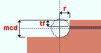
mcd = minimum cope depth
tf = flange thickness
r = cope radiusTo clear this failure message, enter a Cope depth that is larger than the calculated minimum (mcd) or
Cope dimensions exceed allowable limits: This connection failure applies to any beam-to-beam connection (e.g. end plate, clip angle, single-plate shear connection). It indicates that in order to fit the connection being applied to this end of the beam connection design must create a cope that is larger than the cope dimension limits allowed. A cope's width limit is half the beam depth. A cope's length limit is twice the beam depth. This might happen, for example, on a very small beam framing into a very large beam.
Ways that might get you an Input connection type connection are to change the Input connection type, or to change the Section size of one or both of the beams, or to lower the Shear load and thus create a smaller and weaker connection that requires less of a cope.
Before attempting to fix this connection, see the warnings.
Coped beam web stress or buckling exceeded: This connection failure message indicates that the beam cope is too large to stand up to the load on this end.
Some things that you might be able to do without changing to a different Input connection type are to choose a stronger beam Section size, specify a Steel grade with higher yield strength, or to lower the Shear load.
Before attempting to fix this connection, see the warnings.
- D -
Design of rotated connections is not supported: This end connection failure message can be caused by a user-made entry to the Relative rotation connection design lock for a clip angle, bent plate, beam splice or shear connection.
| Lock | Leaf |
| Relative rotation | NS Clip / FS Clip |
| Relative rotation | Bent Plate |
| Relative rotation | Web Plate (for a beam splice) |
| Relative rotation | Shear Tab (on supported, to no supporting member) |
To make this connection failure message go away, you can switch the Relative rotation from
If you want to rotate the connection to an orientation that connection design does not support—that is, to a non-calculated or non-default value—you can enter the number of degrees that you want to Relative rotation and
Before attempting to fix this connection, see the warnings.
Design valid only for 8.8/TB or 8.8/TF bolts: You get this message when AS4100 is the Connection design method and the bolt used for a moment end plate is not an 8.8/TB or 8.8/TF bolt.
Possible ways to get the originally specified Input connection type connection are to choose 8.8/TB or 8.8/TF as the Bolt type or to change to a different Input connection type.
Before attempting to fix this connection, see the warnings.
Design valid only for A325/F1852 or A490/F2280 bolts: You get this message when a bolt type that uses material other than A325/F1852 or A490/F2280 has been entered for a moment end plate (AISC type) For example, if the connection uses a user-defined bolt added to the Bolt Settings, then that bolt must be made of A325/F1852 or A490/F2280 material.
Possible ways to get a system connection are to choose a different moment Bolt type or to change to a different Input connection type.
Before attempting to fix this connection, see the warnings.
Design valid only for A325 or F1852 bolts: This applies to single-plate shear connections. For example, if the connection uses a user-defined bolt added to the Bolt Settings, then that bolt must be made of A325 or F1852 material.
Possible ways to get a system connection are to change the NM bolt type to supported or to change to a different Input connection type.
If the connection uses a user-defined bolt added to the Bolt Settings, then that bolt must be made of A325 or F1852 material.
Before attempting to fix this connection, see the warnings.
Design valid only for class 8.8 bolts: This applies when the Connection design method is EUROCODE 3 or EUROCODE 3 UK. It may apply to a moment end plate (Eurocode type) or to a shear plate, both of which require class 8.8 bolts.
To get the originally specified Input connection type, you need to change the moment Bolt type (for a moment end plate) or the Non moment bolt type to supported (for a shear plate).
Before attempting to fix this connection, see the warnings.
Difference in beam depths > 1-1/4 inches; 32 mm: This applies to beam splice moment connections. Connection design cannot design a beam splice moment connection when that connection is applied to two different S shape or wide flange beams whose Depths differ by more than 1-1/4 inch (32 mm).
Unless you want to change to an entirely different type of connection (e.g. a non-moment splice connection), you will have to change one or both of the beam Section sizes before this connection can be designed.
Before attempting to fix this connection, see the warnings.
Distance between extreme bolts exceeded 530 mm: This end connection failure applies when the Connection design method is EUROCODE 3 or EUROCODE 3 UK. It indicates that connection design cannot create a shear plate connection because the top and bottom bolts in the connection would be farther apart than the limit of 530 mm allowed in the design guide Simple Joints to Eurocode 3.
To get the originally specified Input connection type, increasing the Non-moment bolt diameter may get you a connection with fewer rows of bolts. Or you could lower the Shear load on this end of the beam to cause connection design to create a weaker connection.
Before attempting to fix this connection, see the warnings.
Distance to first row less than minimum required: This beam member end connection failure message can be generated for End Plate and Shear connections under the following conditions:
End Plate: This failure message is generated when Vertical to 1st hole in the non-moment
To clear this failure message, you may be able to adjust the Top of plate in that same
Setting the connection to
Before attempting to fix this connection, see the warnings.
Shear: This failure message is generated when Vertical to 1st hole in the
To clear this failure message, you could try changing the project settings for edge distance or allowable k infringement. Usually the best way to clear the message is to
Setting the connection to
Before attempting to fix this connection, see the warnings.
- E -
End operation will not work with this situation: This connection failure message indicates that the left- or right-end Top flange operation or Bottom flange operation under ![]() End preparations on the member edit window will not work. This is a catch-all failure message. In the table below, situations that produce this failure message (289) are marked "?" or "fail".
End preparations on the member edit window will not work. This is a catch-all failure message. In the table below, situations that produce this failure message (289) are marked "?" or "fail".
| OK = end operation is applicable to the material type. | ||||||
| fail = end operation will not work for this situation (289). | ||||||
| ? = operation works on the flange, not the stem (289). | ||||||
| 288 = failure message number 288. | ||||||
| W, S | C | L | tube | pipe | WT | |
| Cope plain | OK | OK | OK | OK | OK | OK |
| Cope field #3 | OK | OK | ? | fail | fail | ? |
| Cope shop #3 | OK | OK | ? | fail | fail | ? |
| Cut flange width | OK | 288 | 288 | fail | fail | fail |
| Cut flange flush | OK | 288 | 288 | fail | fail | fail |
| Clip flange | OK | fail | fail | fail | fail | fail |
| Notch top/bottom | fail | fail | fail | OK | OK | fail |
| Notch NS/FS | fail | fail | fail | OK | OK | fail |
| Cope field #1 | OK | OK | ? | fail | fail | ? |
| Cope shop #1 | OK | OK | ? | fail | fail | ? |
| Clip web | OK | OK | OK | fail | fail | OK |
| Cope field seismic | OK | OK | ? | fail | fail | ? |
| Cope shop seismic | OK | OK | ? | fail | fail | ? |
Example of ?: Selecting Cope field weld #3 as the Bottom flange operation for a W tee horizontal brace produces the failure message, and a weld preparation will not be applied to the stem of the W tee. However, if you select the same operation as the Top flange operation, the weld preparation will be applied to the top flange of the W tee and, of course, you will not get the failure message. All operations in the above chart that are marked "?" work in a similar way.
To clear the failure message, switch to a different Top/bottom flange operation.
Before attempting to fix this connection, see the warnings.
End plate bending / prying strength exceeded: This failure message applies to end plate connections to which a tension load has been applied. In other words, it applies when the Input connection type is End plate or User defined and a non-zero Tension load has been entered. The failure message may be generated for any Connection design method. It indicates that the bending strength of the end plate has been exceeded.
The connection failure message may be generated due to a user-made entry to the
Assuming that the beam's Tension load is to engineering specifications, generally the best way to clear this failure message is to
Before attempting to fix this connection, see the warnings.
End plate in-plane bending strength exceeded: This connection failure message applies to end plate connections when the Connection design method is EUROCODE 3 UK. It applies when End plate or User defined is the Input connection type. The design check that generates this message is used when the end plate is extended (Extend PL to beam flanges) or when the end plate gage (Gage NS + Gage FS) is more than 1.36 times the end plate depth. The message indicates that the in-plane bending strength of the end plate is exceeded.
The connection failure message may be generated due to a user-made entry to the
Assuming that the beam's Shear load is to engineering specifications, generally the best way to clear this failure message is to
Before attempting to fix this connection, see the warnings.
End plate interferes with beam bottom flange or cope: This end connection failure message can be generated when Plate depth in the non-moment ![]() End Plate leaf has been
End Plate leaf has been ![]() locked to a distance that results in the end plate clashing with the beam's bottom flange or a cope.
locked to a distance that results in the end plate clashing with the beam's bottom flange or a cope.
You can
For some situations, this message may be emitted due to entries made to the number of Rows or Vertical hole spacing in that same
Before attempting to fix this connection, see the warnings.
End plate thickness is greater than maximum: This applies to shear end plate connections (not moment end plates). Per ASD 9th, the maximum thickness for a shear end plate is 3/8 inch (page 4-4). For all other AISC connection design methods, the maximum is 5/8. The CISC maximum thickness for a non-moment shear end plate is 10 mm.
If the Connection design method is CISC 8 or CISC 9 or CISC 10, you may be able to clear this message by checking the box for
If the Connection design method is an AISC method, you may be able to clear this message by checking the box for
Other possible ways to clear this end connection failure message are to increase the strength of plate material used (Steel grade) and thus enable connection design to build a stronger connection, or lower the Shear load and thus get a weaker connection.
Before attempting to fix this connection, see the warnings.
End plate tying resistance/bolt prying strength exceeded: This connection failure message applies to end plate connections with both axial and shear loads. In other words, it applies when the Input connection type is End plate and a non-zero Tension load and/or Compression load has been entered for the end-plate end of the beam along with the automatic or user-entered Shear load. The message may be generated for any Connection design method.
The connection failure message may be generated due to a user-made entry to the
Assuming that the beam end's Shear load and Tension load and Compression load are to engineering specifications, generally the best way to clear this failure message is to
Before attempting to fix this connection, see the warnings.
End plate with 6 or more bolt columns are not supported: This applies to shear end plate connections (non moment). Connection design cannot design end plate connections with more than two bolt columns on each side of the plate.
Connection design does not create shear end plates with 3 or more column bolts on each side of the plate because beam web shear may fail before the bolts fail. Refer to the AISC Steel Construction Manual, Fourteenth Edition, Section J4.2, page 16.1-129.
The connection failure message may be generated due to a user-made entry to the
Before attempting to fix this connection, see the warnings.
End PL invalid 'Pf' refer to AISC design guide 16: This applies when the Connection type is MBMA. According to AISC Steel Design Guide Series 16, Pf is the distance from the bolt centerline adjacent the beam tension flange to the near face of the beam tension flange. You can find pictures of that dimension on pages 22 and 39 of that guide.
MBMA moment end plate connections are used by the metal building industry. Connection design can create such connections for only a limited range of wide flange or S shape or welded plate wide flange sections. Tables 3-6 and 4-7 in the design guide (on pages 22 and 39, respectively) can help you to select a Section size with dimensions comparable to the built-up shapes used in that industry.
Before attempting to fix this connection, see the warnings.
End PL invalid 'Pb' refer to AISC design guide 16: This applies when the Connection type is MBMA. Pb is the distance between adjacent rows of bolts interior to the beam flange. You can find a picture of the Pb dimension on page 20 of the AISC Steel Design Guide Series 16.
MBMA moment end plate connections are used by the metal building industry. Connection design can create such connections for only a limited range of wide flange or S shape or welded plate wide flange sections. Tables 3-6 and 4-7 in the design guide (on pages 22 and 39, respectively) can help you to select a Section size with dimensions comparable to the built-up shapes used in that industry.
Before attempting to fix this connection, see the warnings.
End PL invalid 'g' refer to AISC design guide 16: This applies when the Connection type is MBMA. g is the bolt gage. You can find pictures of the g dimension on pages 22 and 39 of the AISC Steel Design Guide Series 16.
MBMA moment end plate connections are used by the metal building industry. Connection design can create such connections for only a limited range of wide flange or S shape or welded plate wide flange sections. Tables 3-6 and 4-7 in the design guide (on pages 22 and 39, respectively) can help you to select a Section size with dimensions comparable to the built-up shapes used in that industry.
Before attempting to fix this connection, see the warnings.
End PL invalid 'h' refer to AISC design guide 16: This applies when the Connection type is MBMA. h is the total beam depth. You can find pictures of the h dimension on pages 22 and 39 of the AISC Steel Design Guide Series 16.
MBMA moment end plate connections are used by the metal building industry. Connection design can create such connections for only a limited range of wide flange or S shape or welded plate wide flange sections. Tables 3-6 and 4-7 in the design guide (on pages 22 and 39, respectively) can help you to select a Section size with dimensions comparable to the built-up shapes used in that industry.
Before attempting to fix this connection, see the warnings.
End PL invalid 'bp' refer to AISC design guide 16: This applies when the Connection type is MBMA. bp is the end-plate width. You can find pictures of the bp dimension on pages 22 and 39 of the AISC Steel Design Guide Series 16.
MBMA moment end plate connections are used by the metal building industry. Connection design can create such connections for only a limited range of wide flange or S shape or welded plate wide flange sections. Tables 3-6 and 4-7 in the design guide (on pages 22 and 39, respectively) can help you to select a Section size with dimensions comparable to the built-up shapes used in that industry.
Before attempting to fix this connection, see the warnings.
End PL invalid 'tf' refer to AISC design guide 16: This applies when the Connection type is MBMA. tf is the thickness of the beam flange. You can find pictures of the tf dimension on pages 22 and 39 of the AISC Steel Design Guide Series 16.
MBMA moment end plate connections are used by the metal building industry. Connection design can create such connections for only a limited range of wide flange or S shape or welded plate wide flange sections. Tables 3-6 and 4-7 in the design guide (on pages 22 and 39, respectively) can help you to select a Section size with dimensions comparable to the built-up shapes used in that industry.
Before attempting to fix this connection, see the warnings.
End PL invalid 'Pext' refer to AISC design guide 16: This applies when the Connection type is MBMA. Pext is the extension beyond the exterior face of the beam flange. You can find pictures of the Pext dimension on page 39 of the AISC Steel Design Guide Series 16.
MBMA moment end plate connections are used by the metal building industry. Connection design can create such connections for only a limited range of wide flange or S shape or welded plate wide flange sections. Table 4-7 in the design guide (on page 39) can help you to select a Section size with dimensions comparable to the built-up shapes used in that industry.
Before attempting to fix this connection, see the warnings.
End PL material must be 50 ksi (345 MPa) or less: This applies when the Connection design method is ASD13 or LRFD13. It applies when End plate is the Input connection type and Bolted is the Moment type and the moment end plate Connection type is AISC. It indicates that the End plate grade has a yield strength (Fy) that is greater than 50 ksi. Per the AISC Steel Construction Manual, Thirteenth Edition, p 12-9, "The minimum specified yield stress of the end-plate material must be less than 50 ksi."
To get the originally specified Input connection type connection in this situation, you need to select an End plate grade that has a yield strength (Fy) that is less than 50 ksi.
Before attempting to fix this connection, see the warnings.
Eurocode web shear and bending interaction failure:
Extended clip and web doubler not used together: This beam end connection failure message indicates a conflict in ![]() locked variables in the
locked variables in the ![]() Beam Web Doubler and
Beam Web Doubler and ![]() Web Extension Plate leaves. These leaves are available when the designed connection is a clip angle connection, regardless of whether or not the extension plate and/or web doubler is required.
Web Extension Plate leaves. These leaves are available when the designed connection is a clip angle connection, regardless of whether or not the extension plate and/or web doubler is required.
To clear this failure message, you need to take actions that prevent the web doublers and/or web extension plate from being designed.
If the beam web doubler is not required, you can
If the web extension plate is not required, you can
Before attempting to fix this connection, see the warnings.
Extended end PL bolts required top and bottom: This applies when End plate is the Input connection type and Bolted is the Moment type and an axial load (Tension or Compression) has been applied on the same end of a wide flange beam that the end plate welds to in the shop and Top only has been selected as the Location. ![]() Moment End Plate is the name of the leaf containing the relevant connection design locks.
Moment End Plate is the name of the leaf containing the relevant connection design locks.
To get the originally specified Input connection type connection in this situation, you need to select Top and bottom as the Location.
Before attempting to fix this connection, see the warnings.
Extended end pl mom conn, CJP flg-to-pl weld fails: This applies when End plate is the Input connection type and Bolted is the Moment type. ![]() Moment End Plate is the name of the leaf containing the relevant connection design locks.
Moment End Plate is the name of the leaf containing the relevant connection design locks.
The message indicates that the bevel groove weld for shop welding the end plate to the beam flange has failed because the applied moment is too large.
One possible way to get the originally specified Input connection type connection in this situation is to lower the Moment load.
Before attempting to fix this connection, see the warnings.
Extension plate geometry fails due to locked length/width: This connection failure message applies when specific connection design locks have been set in the ![]() NS Clip and/or
NS Clip and/or ![]() FS Clip and Web Extension Plate leaves. Such leaves become available for the design of extend-past-flange clip angles.
FS Clip and Web Extension Plate leaves. Such leaves become available for the design of extend-past-flange clip angles.
The message indicates that the Plate length and/or Plate width of the extension plate is
To clear this message and get a connection, try entering non-contradictory distances to the Plate length and/or Plate width or
Before attempting to fix this connection, see the warnings.
- F -
Flange conn Pl thickness exceeded 3 * tf: This failure message can apply to a bolted or welded moment connection under framing conditions described below.
For a bolted moment connection with flange plates, it results when, in order to design a connection that stands up to the moment on this end of the beam, connection design must create a flange plate that is thicker than the allowed maximum of three times the flange thickness.
For a welded moment connection at the top of a column, you can get this message when, due to the applied moment, the resulting column cap plate would have to be more than 3 times the thickness of the beam flange.
For either the moment flange plate or the moment cap plate, possible ways to get the originally specified connection are to use a beam Section size with a thicker flange or to allow connection design to build a weaker connection by lowering the Moment load on this end of the beam.
Before attempting to fix this connection, see the warnings.
Flange plate bolt shear strength exceeded: This failure message applies to bolted moment flange plates, which may be designed when a wide flange beam frames to a wide flange column web or flange and the Input connection type is Shear or Clip angle or User defined and the Moment type is Bolted. The failure message indicates that the total bolt shear acting on the flange plate bolts exceeds the bolt shear strength.
The connection failure message may be generated due to a user-made entry to the
Assuming that the beam's Moment load and Tension load and Compression load are to engineering specifications, generally the best way to clear this failure message is to
Before attempting to fix this connection, see the warnings.
Flange plate weld strength exceeded: This failure message applies to bolted moment flange plates, which may be designed when a wide flange beam frames to a wide flange column web or flange and the Input connection type is Shear or Clip angle or User defined and the Moment type is Bolted. The failure message indicates that the strength of the flange plate weld to the supporting column has been exceeded.
The connection failure message may be generated due to a user-made entry to the
Assuming that the beam's Moment load and Tension load and Compression load are to engineering specifications, generally the best way to clear this failure message is to
Before attempting to fix this connection, see the warnings.
Frames to a Model Complete member: This applies when the member this beam frames to has its Model complete date set.
You will get a yellow Frames to... banner like the following even if there is no connection failure. This banner describes the framing situation, but does not necessarily pertain to connection design. For more information, click here.
| Frames to a Model Complete member |
In addition to the above banner, you may (but will not necessarily) get a red banner like the following, which indicates a connection failure due to connection design not being permitted to modify the main material of the model-complete member. This can happen, for example, if this beam was added or its connection changed, after the framed-to member's Model complete date was set. Actions that can trigger the changing of a connection include selecting a different Input connection type or adjusting a
Frames to a Model Complete member You can
Framing Situation Likely Cause beam to column The supporting column has its Model complete date set. beam to beam The supporting beam has its Model complete date set.
Framing sit: Shear tab interferes with column stiffener: Applies when connection design attempts to build a single-plate shear connection on this end of this beam and this beam frames to the web of a column on which column stiffeners have been designed for moment connections. Look at this end of the beam in the model, and it should be fairly obvious why you got this connection failure message.
To get a shear connection on this beam, you may be able to edit the other beam (or beams) that frame to the column and remove the column stiffeners that interfere with the design of a shear plate that bolts to this beam. See Design for stiffeners.
Framing sit: Horz offset too small to combine bolts: Applies to offset framing for clip angles or end plates or bent plates.
| Center-to-Center Distances (Standard Fabricator Connections) |
|
| Clip angles: | Wide gage or Narrow gage or Heavy gage, inside or Heavy gage, outside |
| End plates: | Wide gage or Narrow gage |
| Bent plates: | Wide gage or Narrow gage |
When connection design builds offset framing, it attempts to use the appropriate center-to-center distance specified in Standard Fabricator Connections. To line up holes with the opposite connection, connection design may increase the gage on the outstanding leg of the near- or far-side clip angle, but it will not decrease the gage. Instead it generates this connection failure message.
Consequently, one way you might be able to fix this problem is to Move... (or Move...) the member horizontally so that center-to-center distance specified in Standard Fabricator Connections can be used.
Before attempting to fix this connection, see the warnings.
Framing sit: Cannot change OSL dimension: Applies to offset clip angles on opposite sides of a beam or column web.
This error occurs when there is no suitable angle in the Preferred Angle Sizes list in Standard Fabricator Connections that can carry the required gage.
Before attempting to fix this connection, see the warnings.
- H -
Hangar connection not supported: This end connection failure message applies when a beam is vertical.
A beam's end connection may fail with this message when that beam end's Input connection type is Clip angle, End plate, Shear, Fully welded moment connection, Auto standard, or User defined.
Forced hanger connections are supported for columns but not for beams. If you delete the beam and add a column in its place, you may be able to get the connection that you want by selecting Clip angle or Shear as the Input connection type for the column. You will then have to
Before attempting to fix this connection, see the warnings.
HSS reinf plate projects beyond the top of column: This beam end connection failure message applies when a beam end with a welded moment connection frames to a thin-walled HSS/TS column when Use HSS column reinforcement plate is set to Yes.
In order to get reinforcement plates for a welded moment connection, the Top of plate distance entered to the
If this failure message occurred because a user entered a Top of plate that was too large—either directly or by increasing the Length of the reinforcement plate—then the solution is to
Before attempting to fix this connection, see the warnings.
HSS reinf plate weld size greater than maximum allowed: This failure message can apply to a single-plate shear connection or a welded moment connection to a thin-walled HSS/TS column when Use HSS column reinforcement plate is set to Yes.
The message indicates that the weld size for the reinforcement plate to the HSS column needs to be larger than is permitted, possibly because the Plate thickness that is entered in the
To clear this failure message and get a connection, you can try entering a different Plate thickness or Weld size, or you can
Before attempting to fix this connection, see the warnings.
HSS reinf plate thickness greater than maximum allowed: This failure message can apply to a single-plate shear connection or a welded moment connection to a thin-walled HSS rectangular column when Use HSS column reinforcement plate is set to Yes.
HSS wall or W column web yield failure at seat: Applies to a beam with a beam seat connection framing into a tube or W column. It indicates that the column itself (not the connection) is unable to stand up to the load.
Possible ways to get a beam seat are to select a stronger Section size or Steel grade for the column. Or you could lower the Shear load.
Before attempting to fix this connection, see the warnings.
HSS wall strength fails: You get this connection failure message when connection design cannot create a single-plate shear connection on a beam with an axial load to an HSS column or HSS beam because the HSS round (pipe) or HSS rectangular (tube) supporting member is not made of heavy enough material. This failure message may also apply to a moment connection to an HSS column.
To get the originally specified Input connection type connection, you could enter a heavier Section size to the column, or you could lower the Tension load (for a shear connection) or Moment load (for a moment connection) so that connection design can create a weaker connection using the currently entered Section size. You could also specify a Steel grade with a higher yield strength for the supporting column or supporting beam.
For a shear plate connection to an HSS beam or HSS column, you may be able to turn off the design check that caused this failure message by setting Check supporting member for axial load to Never.
Before attempting to fix this connection, see the warnings.
- I -
IMF/SMF connections must have matching load auto flags: A beam-to-column-flange seismic moment connection can be designed when Seismic moment frame member is set to Yes or, possibly, to Automatic and Seismic moment frame type is set to OMF or IMF or SMF or, possibly, to Automatic and the left-end or right-end Moment type is Bolted or Welded. SMF or IMF seismic moment connections can be designed when the Connection design method is any LRFD edition. OMF seismic moment connections can be designed for LRFD and ASD editions.
If the Shear load for an IMF or SMF seismic moment connection is set to
To clear this failure message, try setting both loads to
Before attempting to fix this connection, see the warnings.
IMF/SMF connections not supported for ASD: A beam-to-column-flange seismic moment connection can be designed when Seismic moment frame member is set to Yes or, possibly, to Automatic andSeismic moment frame type is set to OMF or IMF or SMF or, possibly, to Automatic and the left-end or right-end Moment type is Bolted or Welded. SMF or IMF seismic moment connections can be designed when the Connection design method is any LRFD edition. OMF seismic moment connections can be designed for LRFD and ASD editions.
An OMF welded seismic moment connection can be designed for ASD connection design methods, but IMF and SMF connections cannot.
To clear this failure message and get a seismic IMF/SMF moment connection, you could try setting Home > Project Settings > Design > Design Settings > Connection design method to an LRFD edition. But be aware that changing the design method in the middle of a project's development can result in drastic changes that are unanticipated and undesired and cause considerable rework.
Before attempting to fix this connection, see the warnings.
IMF/SMF flange bolt design valid only for A490/F2280 bolts: A beam-to-column-flange seismic moment connection can be designed when Seismic moment frame member is set to Yes or, possibly, to Automatic andSeismic moment frame type is set to OMF or IMF or SMF or, possibly, to Automatic and the left-end or right-end Moment type is Bolted or Welded. SMF or IMF seismic moment connections can be designed when the Connection design method is any LRFD edition. OMF seismic moment connections can be designed for LRFD and ASD editions.
Per Section 7.5 of AISC 358-16, IMF/SMF seismic bolted moment flange bolts must be A490 or F2280.
To clear this failure message and get a seismic IMF/SMF bolted moment connection, try setting the Bolt type on the left-end or right-end
Before attempting to fix this connection, see the warnings.
IMF/SMF flange hole type must be standard round: A beam-to-column-flange seismic moment connection can be designed when Seismic moment frame member is set to Yes or, possibly, to Automatic and Seismic moment frame type is set to OMF or IMF or SMF or, possibly, to Automatic and the left-end or right-end Moment type is Bolted or Welded. SMF or IMF seismic moment connections can be designed when the Connection design method is any LRFD edition. OMF seismic moment connections can be designed for LRFD and ASD editions.
Per Section 7.5 of AISC 358-16, the IMF/SMF seismic bolted moment flange bolt hole type must be standard round.
Before attempting to fix this connection, see the warnings.
IMF/SMF maximum flange bolt diameter is 1 1/8 inch: A beam-to-column-flange seismic moment connection can be designed when Seismic moment frame member is set to Yes or, possibly, to Automatic and Seismic moment frame type is set to OMF or IMF or SMF or, possibly, to Automatic and the left- or right-end Moment type is Bolted or Welded. SMF or IMF seismic moment connections can be designed when the Connection design method is any LRFD edition. OMF seismic moment connections can be designed for LRFD and ASD editions.
Per Section 7.5 of AISC 358-16, the maximum diameter for IMF/SMF seismic bolted moment flange bolts is 1 1/8 inch or 28 mm.
To clear this failure message and get a seismic IMF/SMF bolted moment connection, try setting the Bolt diameter on the left-end or right-end
Before attempting to fix this connection, see the warnings.
Incompatible member sizes: This applies to a beam-to-beam welded moment connection. The message indicates that the supported beam cannot be properly welded to the supporting beam.
You might, for example, get this message in the following situations:
(1) The supported beam's flange is thicker than the flange of the supporting beam, thus making it impossible to weld to the supporting.
(2) The depth of the supported beam is greater than the depth of the supporting beam, thus giving you nothing but air to weld the supported beam's bottom flange to.
(3) The supported beam's bottom flange is aligned with the supporting beam's bottom flange in such a way that makes welding inappropriate (supported's bottom flange bottom face below the supporting's bottom flange top face, but its top face above the supporting's bottom flange).
Before attempting to fix this connection, see the warnings.
Input minus dimension is bigger than allowable field bolt gap in setup: This applies to a beam to beam splice connection with clip angles. The message indicates that the connection has failed because the Input minus dimension on the Beam Edit window is larger than the Home > Project Settings > Job > Bolt Settings > maximum Field bolt gap.
Inside hole spacing is less than minimum: This applies to end plate moment connections. The inside holes are the holes on the end plate that are inside the beam's flanges. The message appears when connection design requires inside holes that are closer together than are allowed. Connection design will have already tried increasing the bolt diameter to as much as 1.5 inches.
Possible ways to get a designed end plate moment connection are to change to a deeper Section size or change from an 8-bolt to a 4-bolt pattern. Or you could use a higher strength Bolt type or to lower the Moment load.
Before attempting to fix this connection, see the warnings.
Insufficient edge distance on supporting flange:
Invalid bolt column edge distance: This beam end connection failure message indicates that an entry has been made to a connection design lock that would result in a horizontal bolt edge distance being too small.
For example, you can get this failure message when, in the
If the per bolt diameter minimum edge distance that is entered as the Default bolt edge distance in Bolt Settings is larger than the minimum in Shear Plate Settings, connection design uses that larger minimum instead of the Shear Plate Settings minimum.
To clear this failure message, you could try redefining the minimum in Shear Plate Settings or Bolt Settings (whichever is larger), then do something on this window (Beam Edit) that causes the connection to be redesigned. Or you could
Before attempting to fix this connection, see the warnings.
Invalid bolt edge distance: This beam end connection failure message indicates that an entry has been made to a connection design lock that would result in a vertical bolt edge distance being too small.
For example, you can get this failure message when, in the
If the per bolt diameter minimum edge distance that is entered as the Default bolt edge distance in Bolt Settings is larger than the minimum in Shear Plate Settings, connection design uses that larger minimum instead of the Shear Plate Settings minimum.
To clear this failure message, you could try redefining the minimum in Shear Plate Settings or Bolt Settings (whichever is larger), then do something on this window (Beam Edit) that causes the connection to be redesigned. Or you could
Before attempting to fix this connection, see the warnings.
Invalid bolt row-column combination: This end connection failure message applies when Shear or User defined or Auto standard is the beam end's Input connection type and, as a result, you get a set of ![]() Shear Tab connection design locks.
Shear Tab connection design locks.
The message indicates that invalid or contradictory entries have been made to Rows and Columns in the
To clear this failure message and get a connection, you could try entering a different number of Rows or Columns, or you could
Before attempting to fix this connection, see the warnings.
Invalid bolt spacing: This beam end connection failure message can apply when Shear, User defined, or Auto standard is the beam end's Input connection type.
You can, for example, get this failure message by doing the following:
- In the
- Lock the Vertical hole spacing to a distance that would, if the connection were designed, result in bolts being too close together per the selected bolt diameter and Connection design method.
To clear the failure message, simply
Before attempting to fix this connection, see the warnings.
Invalid end operation for this type of material: This connection failure message indicates that the Top/bottom flange operation under ![]() End preparations on the member edit window will not work because the Section size of the member is a channel or angle. In the table below, situations that produce this failure message (288) are marked "fail" .
End preparations on the member edit window will not work because the Section size of the member is a channel or angle. In the table below, situations that produce this failure message (288) are marked "fail" .
| OK = end operation is applicable to the material type (288). | ||||||
| fail = invalid end operation for this type of material (288). | ||||||
| 289 = failure message number 289. | ||||||
| W, S | C | L | tube | pipe | WT | |
| Cope plain | OK | OK | OK | OK | OK | OK |
| Cope field #3 | OK | OK | 289 | 289 | 289 | 289 |
| Cope shop #3 | OK | OK | 289 | 289 | 289 | 289 |
| Cut flange width | OK | fail | fail | 289 | 289 | 289 |
| Cut flange flush | OK | fail | fail | 289 | 289 | 289 |
| Clip flange | OK | 289 | 289 | 289 | 289 | 289 |
| Notch top/bottom | 289 | 289 | 289 | OK | OK | 289 |
| Notch NS/FS | 289 | 289 | 289 | OK | OK | 289 |
| Cope field #1 | OK | OK | 289 | 289 | 289 | 289 |
| Cope shop #1 | OK | OK | 289 | 289 | 289 | 289 |
| Clip web | OK | OK | OK | 289 | 289 | OK |
| Cope field seismic | OK | OK | 289 | 289 | 289 | OK |
| Cope shop seismic | OK | OK | 289 | 289 | 289 | 289 |
To clear the failure message, switch to a different Top/bottom flange operation.
Invalid material type for supporting member: You get this message when connection design cannot generate a connection because the supporting member is an invalid material type. You may be able to the originally specified Input connection type connection by changing the Section size on the supporting beam or column.
For a supporting beam: The Section size must be wide flange, channel, HSS/TS (tube), welded plate wide flange, welded plate box or S shape in order for this beam (the supported beam) to connect to that beam.
For a supporting column: The Section size must be wide flange, HSS round (pipe), HSS rectangular (tube), welded plate wide flange, welded plate box or S shape in order for this beam (the supported beam) to connect to that column.
Before attempting to fix this connection, see the warnings.
Invalid material type for this member: You get this message when connection design cannot generate a connection on this beam because the Section size that has been entered is an invalid material type.
To get the originally specified Input connection type connection, you need to change the beam's Section size. For beams, the Section size must be a wide flange or S shape or channel or welded plate W or HSS/TS (tube) or welded plate box (Plain end connections only) in order for you to get a system connection.
Before attempting to fix this connection, see the warnings.
Invalid moments: This applies to a beam-to-beam moment connection. On such a connection, the moments for the opposing beams need to be of equal magnitude and have opposite signs.
To get the originally specified Input connection type connection, try changing the Moment load on one or both of the opposing beams so that the moments are of equal magnitude and have opposite signs.
Before attempting to fix this connection, see the warnings.
Invalid skew to column connection geometry: This connection failure message applies when a connection cannot be designed on a beam connecting to a column at a skewed angle. The exact angle that is not supported depends on the sizes of the members and the connection type. A bolted moment connection to a tube column fails at any skew—other connections are changed under skewed conditions as described under "Also see" below.
Possibly the only way for you to get the originally selected Input connection type is to change the Column rotation so that the beam is no longer skewed.
If you were to
Before attempting to fix this connection, see the warnings.
Also see: For skewed framing situations where the Input connection type is Clip angle or Seated, connection design changes the System designed connection to a Shear connection and gives you a connection changed message instead of failing the connection.
Invalid skewed fillet weld angle between fusion faces: This connection failure message applies when a skewed fillet weld angle is outside of the allowable range specified in the CSA design codes.
This failure will occur if an acute fillet angle is less than 30 degrees or an obtuse angle is greater than 135 degrees referenced from the CSA W59-18 Welded steel construction section 4.5.1.
A way to fix this error would be to utilize a bevel groove weld instead of a fillet when the angle requirement can't be met. An alternate fix would be to adjust the framing such that the shear tab angle to supporting would be within this allowable range.
Before attempting to fix this connection, see the warnings.
Invalid supporting material type for moment connection:
Invalid support material type: You get this message when connection design cannot create the connection specified on this end of this beam (the supported beam) due to the material type of the supporting member (beam or column).
One example: It applies when Shear is selected as the Input connection type on a HSS rectangular beam connecting to an HSS round column—since connection design cannot change to another connection type in this situation, it fails the connection and emits this failure message.
You may be able to get the originally specified Input connection type connection by changing the Section size of the supporting column (or supporting beam).
Before attempting to fix this connection, see the warnings.
Also see: Invalid material type for supporting member (a similar connection failure message).
Invalid weld configuration: This applies to the Shear Tab connection design locks.
The message indicates that, in the Welds section of the
To clear this failure message and get a connection, you could try entering a different NS primary weld type or FS primary weld type or NS primary weld size or FS primary weld size in the Welds section, or you could
Before attempting to fix this connection, see the warnings.
Invalid W section for 8-ten bolt end plate:.This applies when End plate is the Input connection type and Bolted is the Moment type and 8-bolt is the Bolt pattern applies when the Connection design method is ASD 9.
The check that generates this message helps to ensure that, for moment end plates with 8 tension bolts, the section yields before the bolts shear.
Per the Notes for Eight Tension Bolt Type on page 4-122 of ASD9, permissible shapes include sections listed in the Allowable stress design selection table for shapes used as beams, ASD9, page 2-4.
To get this connection, you must change to a different Section size that is wide flange material.
Before attempting to fix this connection, see the warnings.
- L -
Load interaction failed: This failure message may occur for any beam connection that is subjected to a Shear load and an axial load (Tension load or Compression load), or for any moment connection that is subject to a Moment load and an axial load. When a design calculation returns an irrational number for the interaction between, for example, shear and tension, connection design will fail the connection with this failure message.
If you get this failure message for a non-moment connection, lowering the axial load (Tension load or Compression load) should result in connection design returning a non-irrational number for the load interaction, which will clear this failure message.
If you get this failure message for a moment connection, lowering either the Moment load or the axial load should clear this failure message and give you the connection that you want.
Before attempting to fix this connection, see the warnings.
Locked beam web doubler length less than angle length: Beam web doublers may be designed when the beam's Input connection type is Clip angle, Bent plate, Auto standard or User defined.
This beam end connection design failure message indicates that Plate length in the
Before attempting to fix this connection, see the warnings.
Locked bolt edge distance not within required min/max values: This end connection failure message may apply to any connection that is bolted. Minimum and maximum edge distances are based on the connection type, the bolt diameter, design code and other factors.
If you get this failure message, you may be able to
Before attempting to fix this connection, see the warnings.
Locked bolt spacing not within required min/max values: This failure message may apply to any connection that is bolted. Minimum and maximum bolt spacings are based on the connection type, bolt diameter, design code and other factors.
If you get this failure message, you may be able to
One simple example is locking the Vertical edge distance in the
Before attempting to fix this connection, see the warnings.
Locked connection has too many constraints: This is a catch-all failure message that may apply to various connection types or framing situations or loading conditions. It indicates a problem with user-made entries to connection design locks. Connection design may have failed the connection because the ![]() locked settings prevented it from creating a connection of sufficient capacity to stand up to the governing load. Or it may be that locked settings introduced math errors or physical inconsistencies that connection design is unable to resolve.
locked settings prevented it from creating a connection of sufficient capacity to stand up to the governing load. Or it may be that locked settings introduced math errors or physical inconsistencies that connection design is unable to resolve.
Fixing this problem may be as simple as correcting a user-made entry that is inconsistent with related, interdependent entries that are also locked. Or you may have to
If, on the other hand, you do not want to unlock any lockable fields, you might try removing other constraints, such as user-applied setbacks. You also may be able to get the connection you want by lowering the governing load.
Before attempting to fix this connection, see the warnings.
Locked dimension is less than minimum allowed: This end connection failure message typically indicates that a user has made an entry to a connection design lock pertaining to plate dimensions which causes a related dimension to go below the minimum allowed, for example, to a negative number. Or a minimum dimension might be required to allow proper material fitting or welding or to carry the load.
For example, a plate's minimum length may be calculated based on the number of bolt rows that are required in the plate to carry the applied load. If such is the case, then lowering the Shear load may trigger connection design to require fewer bolts and thus clear the failure message and allow the connection to be designed using the user-locked plate length.
Under
The easiest fix for this problem is to simply
To keep the locked distance that you entered without getting a failure message, you will probably have to
Before attempting to fix this connection, see the warnings.
Locked HSS reinf plate length is less than required: This connection failure message can apply to a single-plate shear connection or a welded moment shear plate connection to a thin-walled HSS/TS column when Use HSS column reinforcement plate is set to Yes or possibly to Automatic.
For a single-plate shear connection, the length of the reinforcement plate is required to be 1.5 inches or more than the length of the shear plate. Furthermore, the length of the plate is required to be distributed evenly above and below the shear plate with a minimum top-of-plate distance of 0.75 inch. If a user has entered a Plate length to the
For a welded moment shear plate connection, the length of the HSS column reinforcement plate is required to be 1.5 inches or more than the depth of the beam. If a user has entered a Plate length to the
To clear the failure message and get a connection, the user can increase the Plate length or
Before attempting to fix this connection, see the warnings.
Locked flange plate thickness less than required for carrying moment: This connection failure message applies to a beam with bolted moment connection. You can get this failure message, for example, by entering too small of a Plate thickness in the leaf named ![]() Top Moment Plate or
Top Moment Plate or ![]() Bottom Moment Plate.
Bottom Moment Plate.
Fixing this problem may be as simple as correcting the user-entered Plate thickness or
To clear this message and keep the user-entered flange plate thickness, you will have to lower the Moment load.
Before attempting to fix this connection, see the warnings.
Locked HSS reinf plate top of plate interferes: This connection failure message can apply to a single-plate shear connection or a welded moment connection to a thin-walled HSS rectangular column or TS column when Use HSS column reinforcement plate is set to Yes.
The failure message indicates that an invalid Length or Top of plate in the
For a welded moment connection, the top and bottom edges of the reinforcement plate must be a minimum of 0.75 inch from the top and bottom flanges of the beam.
For a single-plate shear connection, the top and bottom edges of the reinforcement plate must be a minimum of 0.75 inch from the top and bottom edges of the shear plate.
To fix the problem, try entering a different Plate length or Top of plate distance, or
Before attempting to fix this connection, see the warnings.
Locked HSS reinf plate width doesn't fit: This connection failure message can apply to a single-plate shear connection or a welded moment connection to a thin-walled HSS rectangular column or TS column when Use HSS column reinforcement plate is set to Yes.
The failure message indicates that Width in the
To clear this failure message and get a connection, try entering a different Width, or try
Before attempting to fix this connection, see the warnings.
Locked OSL bolts and opposite connection interfere: This connection failure message applies to a beam with a connection (clip angle or end plate or bent plate or stability angle) that bolts to a beam web or column web and shares bolts with the connection on the opposite side of the web.
The connection failure message is generated during the Framing situations checking phase of Process and Create Solids when framing situation checking is unable to reconcile the two connections due to connection design locks in one or both of the connections.
An approach to fixing this problem might begin with identifying those connection design locks in the two connections that pertain to bolt design. If you want connection design of shared bolts to be governed by the connection design locks in the connection on the opposite side of the web, try
Before attempting to fix this connection, see the warnings.
Locked plate/angle length results in less than minimum bolt rows: This connection failure message applies to a beam with a non-moment end plate connection. The connection design locks for such a connection are contained in a leaf named ![]() End Plate. The message may also apply to certain clip angle connections.
End Plate. The message may also apply to certain clip angle connections.
The message results from the Plate depth entered to the
To clear this failure message and get a connection, try entering a different Plate depth, or
Before attempting to fix this connection, see the warnings.
Locked rows is less than required for extension clip angle: This connection failure message applies to extended clip angles, which can be designed when the Shear load is sufficiently high and the connection specification Extend past flange is set to If required.
The message indicates that connection design is unable to extend the clip angle past the bottom flange of the beam because a user has entered too small of a number of Rows.
To clear this failure message and get a connection, try entering a larger number of Rows (to supporting) and/or Rows (to supported), or
Before attempting to fix this connection, see the warnings.
Locked rows result in connection geometry failure: This connection failure message may apply when Clip angle, Auto standard, or User defined is the Input connection type If may also apply to other connection types.
For a clip angle, the message might, for example, indicate that a user has entered a number of Rows (to the supported beam's web) for the
For other connection types or other situations with clip angles, you can try entering a different number of Rows, or you can
Before attempting to fix this connection, see the warnings.
Locked top of plate should be a negative value: This connection failure message may apply when End plate is the Input connection type and Bolted is the Moment type and part of the moment end plate projects above the supported beam's top flange. Most moment end plates extend above the top flange.
The message indicates that the user has entered a non-negative distance to Top of plate in the
To clear this failure message and get a connection, you can try entering a negative Top of plate or you can
Before attempting to fix this connection, see the warnings.
Locked vertical to 1st hole less than minimum required or minimum setup value: This end connection failure message can apply to clip angle and bent plate connections.
The failure message is generated when a user has entered an unpermitted Vertical to 1st hole distance in the
To clear this failure message and get a connection, you can try entering a different Vertical to 1st hole (leg to supported) or Vertical 1st hole (leg to supporting), or you can
Before attempting to fix this connection, see the warnings.
Locked welded tee length greater less than maximum allowed: This end connection failure message can apply when a welded tee has been designed for a beam-to-beam connection. To get a welded extended tee, the connection type must be a clip angle or bent plate or end plate, and ![]() Extended welded tee must be checked in the
Extended welded tee must be checked in the ![]() Connection specifications leaf.
Connection specifications leaf.
The connection failure message may be generated when the entry to Tee length is greater than the depth of the supporting beam.
Unlocking
Before attempting to fix this connection, see the warnings.
Locked welded tee length less than minimum required: This end connection failure message can apply when a welded tee has been designed for a beam-to-beam connection. To get a welded extended tee, the connection type must be a clip angle or bent plate or end plate, and ![]() Extended welded tee must be checked in the
Extended welded tee must be checked in the ![]() Connection specifications leaf.
Connection specifications leaf.
The connection failure message may be generated due to Tee length and, for example, Tee flange thickness or Tee web thickness being
One possible way to clear this failure message is to decrease the beam end's Shear load in the
Before attempting to fix this connection, see the warnings.
Long-slot not permitted in combination with slots/oversize holes in other plies: This happens when the connection material is bolted to the beam's Main Material
To clear this connection failure and generate a passing connection, select an allowable combination of hole types, such as Long slots and Standard round (SC bolts are required).
- M -
Max beam slope exceeded for hss beam with end plate and axial load: This connection failure message applies to an HSS beam that has End plate as the Input connection type Extend PL to beam flanges and with an axial load (Tension or Compression).
To get the originally specified Input connection type connection, try changing the End elevation on one end of the beam to lessen the slope of the beam.
Before attempting to fix this connection, see the warnings.
Max beam slope exceeded for a moment connection: This connection failure message applies to the failure of a sloping bolted moment connection, or to a sloping welded moment to tube or W column flange, or to a sloping welded moment connection to W column web. It indicates that the beam slopes too much. Connection design cannot create moment connections on beams that slope more than 30 degrees.
To get the originally specified Input connection type connection, try changing the End elevation on one end of the beam to lessen the slope of the beam.
Before attempting to fix this connection, see the warnings.
Maximum bolt diameter is 1 1/4 in; 31 mm:
| No longer applies! |
Prior to v2018, connection design had prevented beam seats and clip angle connections from being designed using bolts with a diameter greater than 1 1/4 in or 31 mm. That design check has been removed, and this connection failure message no longer applies.
Maximum number of bolt rows exceeded: You get this message when, in order to meet loading conditions, connection design must, for example, design a single-plate shear connection with more than the maximum number of rows. The maximum is based on the connection type and connection design method and can be calculated by dividing the minimum bolt spacing per bolt size and the top and bottom edge distances into the available space. For the example of a beam-to-beam shear plate connection, the available space for a shear plate extended to both k's of a supporting beam might be the supporting beam's depth - (2 * k distance). However, if the supported beam's depth is less than the supporting beam's depth, the actual available space is limited by the supported beam's depth since connection design will not add bolt rows below the depth of the supported beam but will instead emit the fail message Connection will not fit in beam.
A possible way to clear this failure message is to lower the Shear load and thus create a weaker connection. Lowering the number of rows in the
You could try to
Before attempting to fix this connection, see the warnings.
Maximum plate seat slope exceeded: You get this message when Seated is the connection type and Plate is selected as the connection material. The message indicates that connection design is unable to create a plate seat because the supported beam slopes more than 30 degrees from horizontal.
One way to possibly get a connection is to change the supported beam's (this beam's) left or right End elevation so that it slopes 30 degrees or less.
Or you could change the beam's Input connection type to Bent plate, End plate, or Shear.
Before attempting to fix this connection, see the warnings.
Member moment strength exceeded: This message applies to moment connections. It indicates that the beam is overstressed due to moment forces.
Possible ways to get the originally specified Input connection type connection and moment settings include inputting a stronger beam Section size, changing the Steel grade to a steel with higher yield strength, or to lowering the Moment load. For welded or end plate moment connections, you can check the box for Design moment connections for greater than 100% in Design Settings. For bolted moment flange plates, holes in the flange may be too large in diameter, and this can be fixed by decreasing the Bolt diameter of those bolts.
Before attempting to fix this connection, see the warnings.
Member must frame into a concrete member: You can get this message when Bearing is the beam end's Input connection type and that beam end does not frame to a concrete wall or tilt-up panel.
To get the originally specified Input connection type connection, you need to add a concrete wall or tilt-up panel for the beam to frame to.
Changing the Input connection type connection to a different connection type should also clear this failure message.
Before attempting to fix this connection, see the warnings.
Minimum weld metal ten. strength = 60 ksi (414 MPa): This message applies to several connection types.
Connection design cannot create certain connections unless the Weld material tensile strength at Home > Project Settings > Job > Weld Design Settings is set to 60 ksi (414 MPa) or greater.
You should report this problem to qualified personnel who know what type of welding equipment you will be using.
Before attempting to fix this connection, see the warnings.
Minimum weld metal ten. strength is 70 ksi ; 483 MPa: This message applies to single-plate shear connections (shear tab connections) when the Connection design method is any ASD or LRFD edition. Calculations used to size welds for a shear plate connection are based on the assumption that the weld tensile strength is at least 70 ksi.
Connection design generates this failure message for shear tab connections whose Weld material tensile strength at Home > Project Settings > Job > Weld Design Settings is less than 70 ksi (483 MPa).
You should report this problem to qualified personnel who know what type of welding equipment the fabricator will be using.
Before attempting to fix this connection, see the warnings.
Minimum weld metal tensile strength is 490 MPa: This message applies to single-plate shear connections (shear tab connections) when the Connection design method is a Canadian edition (CISC8, CISC9, or etc.). Calculations used to size welds for a shear plate connection are based on the assumption that the weld tensile strength is at least 490 MPa.
Connection design generates this failure message for shear plate connections whose Weld material tensile strength at Home > Project Settings > Job > Weld Design Settings is less than 490 MPa. To stop getting this failure message, you need to increase the Weld material tensile strength to at least 490 MPa.
You should report this problem to qualified personnel who know what type of welding equipment the fabricator will be using.
Before attempting to fix this connection, see the warnings.
Moment bolt row in 4/8-bolt pattern end plate should not be modified: This end connection failure message can apply when a beam's end has its Input connection type set to End plate and—under ![]() Moment options—its Moment type is set to Bolted and its Bolt pattern is set to 4-bolt or 8-bolt.
Moment options—its Moment type is set to Bolted and its Bolt pattern is set to 4-bolt or 8-bolt.
The message may be generated due to
To get a connection with the number of bolt rows that you want, you can open the
To clear this message and get a different number of Rows of bolts, you can change the Bolt pattern from 4-bolt to 8-bolt or from 8-bolt to 4-bolt.
Before attempting to fix this connection, see the warnings.
Moment conn not supported with through plate connection: You get this message when you attempt to apply ![]() Moment options to a shear through plate connection.
Moment options to a shear through plate connection.
To get the originally specified Input connection type connection, you need to set Through shear plate to No or change the Moment type to Non-moment.
Before attempting to fix this connection, see the warnings.
Moment end plate thk. less than reqd. for bending stress: This failure message applies to moment end plates (any type). In other words, it applies when End plate is the Input connection type and Bolted is the Moment type. It may be generated for any Connection design method.
The message indicates that the moment end plate thickness is not sufficient to accommodate the bending stress that the connection is subjected to.
The message may be generated due to user-made entries to
Assuming that the Moment load and end plate dimensions, etc. are what they are supposed to be, the best way to clear the failure message is to
Before attempting to fix this connection, see the warnings.
Moment/extended end plate width less than beam flange width: This applies to a moment end plate or an extended end plate when the end plate width is less than the beam flange width.
This connection failure is caused by the connection design locks for Plate width NS and/or Plate width FS when they are
To fix this connection failure,
Before attempting to fix this connection, see the warnings.
Moments at conn must be equal but opposite sign: This applies to both bolted and welded beam-to-beam moment connections. For such connections, the Moment load on the opposing supported beams must be of equal magnitude and have opposite signs to prevent twisting of the supporting beam.
To get a beam-to-beam moment connection, you need to enter exactly the same Moment load on each of the two supported beams except that a negative sign (-) must be entered in front of one of the moment loads. This means that if you enter 1000 to one of the supported beams, you must enter -1000 for the opposite supported beam.
Before attempting to fix this connection, see the warnings.
More than 2 columns of bolts on shear connection: This applies to shear plate moment connections. It results when connection design requires more than two columns of bolts in order to make the connection strong enough to withstand the load on this end of the beam.
You may be able to get the originally specified Input connection type connection by lowering the Shear load. Or you could use stronger bolts (NM bolt type to supported). Since connection design has probably already incremented the bolt sizes to maximum, changing the NM bolt diameter probably will not help.
Before attempting to fix this connection, see the warnings.
More than 4 bolt cols reqd for ea side of splice: This message applies to beam-to-beam splice plate connections. It results when connection design requires more than four bolt columns in order to make the connection strong enough to withstand the load on this end of the beam.
A possible way to get a splice plate with four or fewer bolt columns is to lower the Shear load. This will result in a weaker connection.
Before attempting to fix this connection, see the warnings.
More than 4 cols of bolts in web doubler: This connection failure message results when, in designing a web doubler to compensate for a cope that fails, connection design requires more than 4 columns of bolts in order for the connection to stand up to the calculated load.
Before attempting to fix this connection, see the warnings.
More than 10 bolt rows reqd for web connection: This connection failure message may apply to any beam web shear connection. It is caused when connection design requires more than 10 rows of bolts to support the calculated load on this end of the member. Since connection design does not support more than 10 rows of bolts for a web connection, the connection fails.
Possible ways to get connection design to design the originally specified Input connection type are to lower the Shear load or to specify a Steel grade with higher yield strength.
Before attempting to fix this connection, see the warnings.
More than 30 bolt rows required in flange connection: This applies to any beam-to-beam or beam-to-column bolted moment connection. It results when in order to design a connection strong enough to stand up to a moment reaction on this end of the beam, connection design requires more than the maximum of 30 rows of bolts.
For a beam-to-beam splice connection, in the
Other possible ways to get a bolted moment system connection with fewer than 30 rows of bolts are to lower the Moment load, thus making the connection weaker, or to change the Steel grade so that stronger materials are used, thus making the connection stronger.
Before attempting to fix this connection, see the warnings.
- N -
Net/gross area conn strength fails: This connection failure message indicates that the connection on this end of the beam is overstressed.
Since it is the connection that is overstressed, using stronger materials for the beam will not help. You could, however, lower the Tension load on the beam.
Before attempting to fix this connection, see the warnings.
No supporting member: This applies to a connection on the end of a beam that does not frame to a supporting beam or column.
One way to get the originally specified Input connection type connection is to Add Beam or Add Column to generate a supporting member.
You can also change the Input connection type to Clip angle or Bent plate or End plate. Connection design is able to generate these types of system connection s on a beam that does not frame to a supporting member. Also, if the Input connection type is Shear and the Material type is Plate, setting Attached to to Supported will allow a single-plate shear connection to be generated in the model without a supporting member.
Before attempting to fix this connection, see the warnings.
Non-moment connection has user moment load: This applies to beams with non-moment connections that have non-zero user moment loads.
To clear this connection failure, change the Moment type to Bolted or Welded. If you do not want a moment connection, set the Moment load to
or enter a value of zero, then change the Moment type to Non-moment.
Number of bolt columns is greater than 3: This applies to shear through plate connections, which only allow three columns of bolts. It results when, in order to design a connection sufficiently strong to meet the load, connection design requires more than three columns of bolts, which is not supported.
A possible way to get a shear through plate system connection with three or fewer bolt columns is to lower the Shear load and thus design a weaker connection.
Before attempting to fix this connection, see the warnings.
- O -
Only welded flange OMF supported for 15th edition: A beam-to-column-flange seismic moment connection can be designed when Seismic moment frame member is set to Yes or, possibly, to Automatic and Seismic moment frame type is set to OMF, IMF, SMF, or (possibly) to Automatic and the left-end or right-end Moment type is Bolted or Welded. SMF or IMF seismic moment connections can be designed when the Connection design method is any LRFD edition. OMF seismic moment connections can be designed for LRFD and ASD editions.
For ASD15 and LRFD 15, connection design only allows welded moment shear tab connections to be used in an OMF (ordinary moment frame). This is based on Sections E1.6b.(c)(2) and E1.6b.(c)(5).
Possible ways to clear this failure message are to change the Seismic moment frame type to IMF or SMF. If you want to keep using OMF design, you could try changing the Moment type to Welded.
Before attempting to fix this connection, see the warnings.
Option to replace web doubler with large clip L fails: This connection failure message indicates that the box for Replace doubler with larger clip is checked on the Beam Edit window and there was no suitable angle in the Preferred Angle Sizes list in Standard Fabricator Connections.
To get the originally specified Input connection type connection, try adding more angles to the Angles list. Or uncheck the box for
Before attempting to fix this connection, see the warnings.
OSL bolt shear strength exceeded for comb. shear and axial load: This connection failure message applies to clip angle connections with both axial and shear loads. In other words, it can apply when the Input connection type is Clip angle or Auto standard or User defined and a non-zero Tension load and/or Compression load has been entered for the clip-angle end of the beam along with the automatic or user-entered Shear load. The clip angle's Attachment to supporting must be Bolted. The message may be generated for any Connection design method.
Assuming that the outstanding leg (OSL) is the leg to the supporting beam or column, this connection failure message may be generated due to a user-made entry to the
Assuming that the beam end's Shear load and Tension load and Compression load are to engineering specifications, generally the best way to clear this failure message is to
Before attempting to fix this connection, see the warnings.
OSL bolt tension capacity exceeded: This connection failure message applies to clip angle or end plate connections to which a tension load has been applied. It can also apply to end plate connections. In other words, it may apply when the Input connection type is Clip angle, End plate, or User defined and a non-zero Tension load has been entered. The clip angle's Attachment to supported connection specification needs to be set to Bolted. The failure message may be generated for any Connection design method. It indicates that the bolt tension capacity on the end plate or on the outstanding leg of the clip angle has been exceeded.
For a clip angle, this connection failure message may be generated due to a user-made entry to the
Assuming that the beam's Tension load is to engineering specifications, generally the best way to clear this failure message is to
Before attempting to fix this connection, see the warnings.
- P -
Paddle plate weld strength exceeded: You can get this end connection failure message when an HSS/TS beam end's Input connection type is Clip angle and ![]() Use paddle plate is turned on (checked) in
Use paddle plate is turned on (checked) in ![]() Connection specifications. The connection can also be emitted when the Input connection type is Shear and
Connection specifications. The connection can also be emitted when the Input connection type is Shear and ![]() Use paddle plate is turned on in the connection specifications for shear connections.
Use paddle plate is turned on in the connection specifications for shear connections.
In the
You might be able to clear this failure message by lowering the relevant beam end's Shear load, but it is generally a better idea to make adjustments to Width and the Weld size.
Before attempting to fix this connection, see the warnings.
Physical limitations exceeded: This is a catch-all connection failure message.
Ways to diagnose the problem are to review the 3D model, generate a Connection Design Calculations report, or generate an Expanded Connection Design Calculations report and evaluate which formulas apply to the situation.
Checking the box for
Before attempting to fix this connection, see the warnings.
Plate is thicker than maximum: This connection failure message may apply to a through plate shear connection or to single-plate shear connections or to beam splices.
For shear through plates: When connection design tries to make the connection strong enough to stand up to the load on the end of the beam, the design of the through plate connection will fail if connection design determines that plate material must be greater than 1.5 inches thick. Possible ways to get a Through shear plate system connection are to specify a higher strength Steel grade, or to create a weaker connection using thinner plate material by lowering the Shear load. You could also try to change the
For single-plate shear connections: This also applies to an extended shear plate to column web. AISC specifies that the maximum plate thickness for single-plate shear connections be half the bolt diameter plus 1/16 of an inch. Connection design fails connections that are thicker than this. To turn this design check off (so that connection design passes the connection), check the box for Design non-AISC single-plate shear connections.
For beam splices, you will most likely get this failure message if you have specified that the splice be designed on the Near or Far side of the beams' webs. If such is the case, switching the Side to Both will allow connection design to generate a stronger connection with spice plates on both sides of the beams' webs.
Before attempting to fix this connection, see the warnings.
Plate to flange weld strength exceeded: This connection failure message applies to moment end plate connections on wide flange beams. In other words, it applies when End plate is the Input connection type and Bolted is the Moment type. It may be generated for any selected Connection design method. The message indicates that the strength of the flange-to-plate weld is insufficient.
Before attempting to fix this connection, see the warnings.
Pull through strength on flg-pl/bm-flg exceeded: This failure message applies to bolted moment flange plates, which may be designed when a wide flange beam frames to a wide flange column web or flange and the Input connection type is Shear, Clip angle, or User defined and the Moment type is Bolted. The message indicates that the moment load exceeds the moment carrying capacity of either the flange plate or the beam flange (whichever is the minimum).
Most likely you will get the Flange plate bolt shear strength exceeded failure message before you get this message. However, there may be conditions under which this connection failure message may be generated due to a user-made entry to the
Assuming that the beam's Moment load, Tension load, and Compression load are to engineering specifications, generally the best way to clear this failure message is to
Before attempting to fix this connection, see the warnings.
Plate/supporting member bearing strength exceeded: This connection failure message applies to moment end plates (any type). In other words, it applies when End plate is the Input connection type and Bolted is the Moment type. It may be generated for any Connection design method. The message indicates that the bearing strength of the end plate or the supporting column is exceeded.
The connection failure message may be generated due to user-made entries to
Assuming that the column section size and applied Moment load are to engineering specifications, the best way to clear this failure message is to make adjustments to the offending locks, either by making different entries or by
Note: When adjusting row spacing on a moment end plate, you will probably get the Bolt tension capacity exceeded for moment end plate conn. or Moment end plate thk. less than reqd. for bending stress failure messages before you get this one.
Before attempting to fix this connection, see the warnings.
- R -
Required bolt columns greater than maximum allowed: This failure message applies to shear plate connections, including through plate connections and single-plate shear connections. It indicates that connection design has already attempted to increase the diameter of connection bolts and the number of rows of connection bolts to the maximum allowed and cannot add a new column of bolts because the additional column would make for more columns than are allowed.
Under most conditions, the maximum number of bolt columns that connection design can employ in a design is 2. See Try two-bolt-column shear tabs. However, you can use connection design locks to specify 3 or even more columns of bolts, and connection design will attempt to design a shear plate using that number of columns of bolts.
One possible fix that you can employ without increasing the number of columns of bolts is to increase the bolt size. However, since the design routines for shear plates use the list of Available bolt diameters, it is likely that connection design has already tried the maximum size of bolt that is available on that list.
Another possible fix is to increase the depth of the beam Section size to allow more rows of bolts.
Still another possible fix is to lower the Shear load and thus allow connection design to create a weaker connection.
Before attempting to fix this connection, see the warnings.
Required bolt dia. is greater than the maximum available: This applies to single-plate shear connections (shear tabs). It indicates that connection design attempted to find a bolt diameter that it could use, but none was available on Bolt Settings window, under Available bolt diameters.
To get the originally specified Input connection type connection, try entering a larger NM bolt diameter on the Beam Edit window. Do not select the diameter in that field's
When incrementing bolt sizes, connection design is able to choose only those bolts that are
Still another way to get connection design to generate a connection is to lower the Shear load and thus allow a weaker connection—with smaller-diameter bolts—to be designed.
To see the offending bolt diameter that connection design was testing for when it failed the connection, you can
Before attempting to fix this connection, see the warnings.
Rolled beam moment connection is not supported: You get this message when a rolled beam has a moment connection.
To get the originally specified Input connection type moment connection, you can change the Rolling operation to Camber annotation or None.
To get a non-moment Input connection type connection on a rolled beam, change the Moment type to Non-moment.
Connection design cannot build moment connections on rolled beams.
Before attempting to fix this connection, see the warnings.
- S -
Safety seat angle design strength fails: This connection failure message indicates that connection design has failed the angle safety seat because it is unable to stand up to the dead weight of the beam. Only two bolts support a system-designed safety seat, so it is most likely that these bolts are the reason for the connection failure. In v2019, the introduction of safety seats that weld to the column also made it possible for this failure message to be generated due to weld insufficiency. Connection design can be instructed to design safety connections for clip angle, bent plate, end plate or shear connections on wide flange beams framing to a W column web.
To get the originally specified Input connection type connection, you might first try to select No for the Use a safety erection seat option under
Or you could use a lighter Section size for the beam and thus decrease its dead weight.
Before attempting to fix this connection, see the warnings.
Safety seat won't fit in supporting beam web: You can get this failure message on a beam that is set to ![]() Use a safety erection seat frames to the web of another beam, resulting in what would be a clash if the safety seat were designed. If the supporting beam is a wide flange, the safety seat cannot infringe upon the k distance of the supporting beam. Since the safety seat fails, the Input connection type connection—for example, a clip angle—is also not designed.
Use a safety erection seat frames to the web of another beam, resulting in what would be a clash if the safety seat were designed. If the supporting beam is a wide flange, the safety seat cannot infringe upon the k distance of the supporting beam. Since the safety seat fails, the Input connection type connection—for example, a clip angle—is also not designed.
You might be able to, for example, switch the Location of safety erection seat from Bottom to Top to fix this problem.
Another possible fix would be to adjust the left and right End elevation of the beam. Both end elevations would have to be made the same since a safety seat cannot be designed on a sloping beam.
You could also enter a deeper Section size of the supporting beam.
To find an appropriate angle, connection design searches the Preferred Angle Sizes list first, then (if it can't find one), searches the local shape file. You might be able to adjust the Preferred Angle Sizes list so that a smaller angle is used then mark both beams for processing and then Process > Precess and Create Solids to bring about the desired change.
Before attempting to fix this connection, see the warnings.
SC bolts required for eccentric bolts in long-slotted holes: This happens when the connection material is bolted to the beam's Main Material
To clear this connection failure and generate a passing connection, set the NM bolt type to supported to an SC bolt type.
SC bolts required for eccentric bolts in short-slotted holes: Clause 14.3.5.2(b)(ii) requires that SC bolts be used if a bolt in a short slot is loaded eccentrically.
This can be fixed by changing the hole type to standard round or oversize or by changing the bolt to a slip-critical bolt type.
Note: This is unique to AS4100. Other design methods require an SC bolt if there are short slots in multiple plies or a long slot. There are other fail statements for these conditions that are used by other design methods.
SC bolts required for eccentric bolts with short-slotted holes in multiple plies: This happens when the connection material is bolted to the beam's Main Material
To clear this connection failure and generate a passing connection, set the NM bolt type to supported to an SC bolt type.
SC bolts required for slots loaded parallel to slot: Clause 14.3.5.2(b)(ii) and (iii) requires that SC bolts be used if a bolt is in a slot and loaded in a direction parallel to the slot.
This can be fixed by changing the hole type to standard round or oversize or by changing the bolt to a slip-critical type.
Note: This unique fail statement was made for AS 4100, because AS 4100 allows bearing-type bolts in an oversize hole. All other design methods use the fail statement "SC bolts required for slots or oversize holes".
SC bolts required for slots or oversize holes: This end connection failure message indicates that slip critical bolts are required in a clip angle (leg to the beam web) or single-plate shear connection with slots when there is an axial load (Tension or Compression) on the beam or on any single-plate shear connection with oversized holes.
To get the originally specified Input connection type connection, you need to select slip critical bolts (e.g., A325SC) as the NM bolt type to supported.
Seated connection stiffener fails in buckling: This end connection failure message can apply when the beam end's Input connection type is Seated and Seat material in ![]() Connection specifications is set to Plate.
Connection specifications is set to Plate.
You can get this failure message because—in the
You might be able to clear this failure message by lowering the relevant beam end's Shear load, but it is generally a better idea to adjust the Plate thickness.
Before attempting to fix this connection, see the warnings.
Seated connection weld fails in shear: This end connection failure message can apply when the beam end's Input connection type is Seated and Seat material in ![]() Connection specifications is set to Plate.
Connection specifications is set to Plate.
In the
You might be able to clear this failure message by lowering the relevant beam end's Shear load, but it is generally a better idea to make adjustments to the stiffener plate Depth and the Stiffener weld size.
Before attempting to fix this connection, see the warnings.
Seat length less than minimum required: This end connection failure message can apply when the beam end's Input connection type is Seated and Seat material in ![]() Connection specifications is set to Plate.
Connection specifications is set to Plate.
In the
Setting the connection to
Before attempting to fix this connection, see the warnings.
Seat strength failure: This applies to beam-to-column beam seats. It is caused when connection design tries to create a seat with a width or length larger than 20 inches (51 mm) or a depth larger than a dimension that depends on the framing situation.
One way to fix this problem is to lower the Shear load so that connection design creates a weaker seat, possibly with a width, length or depth that is below the maximum, thus causing the seat to pass.
Another possible fix is to change the Input connection type on this end of the beam to a Clip angle.
Before attempting to fix this connection, see the warnings.
Seat width less than minimum required: This end connection failure message can apply when the beam end's Input connection type is Seated and Seat material in ![]() Connection specifications is set to Plate.
Connection specifications is set to Plate.
In the
Before attempting to fix this connection, see the warnings.
Seismic moment connection only allowed to column flange: A beam-to-column-flange seismic moment connection can be designed when Seismic moment frame member is set to Yes or, possibly, to Automatic and Seismic moment frame type is set to OMF or IMF or SMF or, possibly, to Automatic and the left-end or right-end Moment type is Bolted or Welded. SMF or IMF seismic moment connections can be designed when the Connection design method is any LRFD edition. OMF seismic moment connections can be designed for LRFD and ASD editions.
Connection design cannot create a seismic moment connection for a beam to a column web. Rotating the column might get you a connection.
Connection design also does not support seismic beam splice moment connections.
Before attempting to fix this connection, see the warnings.
Seismic moment connection is not prequalified: A beam-to-column-flange seismic moment connection can be designed when Seismic moment frame member is set to Yes or, possibly, to Automatic and Seismic moment frame type is set to OMF or IMF or SMF or, possibly, to Automatic and the left-end or right-end Moment type is Bolted or Welded. SMF or IMF seismic moment connections can be designed when the Connection design method is any LRFD edition. OMF seismic moment connections can be designed for LRFD and ASD editions.
This connection failure message is emitted when you specify a moment connection that is not prequalified per AISC 358 for an SMF (special moment frame) or IMF (intermediate moment frame).
Setting the beam's Input connection type to Shear might clear this failure message.
Before attempting to fix this connection, see the warnings.
Shear and bending interaction fails at the notch: This applies when the Connection design method is EUROCODE 3 or EUROCODE 3 UK. It applies to non-moment end plate connections and single-plate shear connections on a wide flange beam that is coped at the top (or at both the top and the bottom), presumably so that the beam can frame to the web of another wide flange beam. It indicates that the coped beam section (on this beam) is not strong enough to stand up to the Shear load.
To get the originally specified Input connection type without changing the framing condition, you could change this beam's Section size to a wide flange with a thicker web or use a stronger Steel grade. Or you could lower the Shear load on this end of the beam to permit connection design to create a weaker connection.
Changing the specified Input connection type to Clip angle and specifying If required for Create web doublers is a possible way to get a system connection using the originally specified load and beam section size.
Before attempting to fix this connection, see the warnings.
Shear plate buckling strength exceeded: This failure message applies to shear plate connections. You can get a single-plate shear connection as a beam-to-beam connection or a beam-to-column connection when Shear is the Input connection type and Plate is the Material type. The message indicates that the shear plate buckling strength has been exceeded for the axial and shear load that has been applied to this end of the supported member (this beam).
The connection failure message may be generated due to a user-made entry to the
Assuming that this beam's Shear load and Tension load are to engineering specifications, generally the best way to clear this failure message is to
Before attempting to fix this connection, see the warnings.
Shear plate flexure strength exceeded: This failure message applies to shear plate connections. You can get a single-plate shear connection as a beam-to-beam connection or a beam-to-column connection when Shear is the Input connection type and Plate is the Material type. The message indicates that, when considering eccentricity of load, the shear capacity of the shear plate is exceeded.
The connection failure message may be generated due to a user-made entry to the
Assuming that this beam's Shear load and Tension load and Compression load are to engineering specifications, generally the best way to clear this failure message is to
Before attempting to fix this connection, see the warnings.
Shear plate grade must be S275 or S355: This applies when the Connection design method is EUROCODE 3 or EUROCODE 3 UK. It indicates that connection design cannot create a shear plate connection because the steel grade used does not contain S275 or S355.
To fix this problem for an individual shear plate, you can change the Shear plate grade in Connection Specifications to a grade whose name contains S275 or S355 on the Beam Edit window. The setup option that sets the default plate material grade for all shear plates when Shear plate grade is set to
Before attempting to fix this connection, see the warnings.
Shear tab material max Fy = 50 ksi; 344 MPa: This applies to single-plate shear connections (shear tab connections).
To get a shear tab system connection, the steel must have a yield strength less than or equal to 50 ksi (344 MPa). The yield strength (Fy) of steel grades for plate material is set at Home > Project Settings > Job > Steel Grade - Plates. To fix this problem, you can change the Home > Project Settings > Fabricator > Standard Fabricator Connections > Plates > the Shear Plates section > Plate material grade.
Before attempting to fix this connection, see the warnings.
Shear tab max. bolt diameter is 1 1/8 inch; 28 mm:
| No longer applies! |
The maximum bolt diameter restriction has been lifted for single-plate shear connections (shear tabs), and this connection failure message no longer applies.
If you want connection design to be able to properly design shear tabs for bolt diameters that are larger than 1 1/8 inch (28 mm), you should make appropriate entries to Bolt spacings setup in Connection Detailing/Fabricator Options.
Shear/Tension/Comp load less than minimum required by AS4100: This connection failure message applies when the Connection design method is AS4100.
The message indicates that you have entered a Shear load or Tension load or Compression load of less than 40 kN (9 kips imperial). When the Input connection type is a choice other than Plain end, any load that you enter to these fields must be 40 kN or greater, except as described in the next paragraph. To make the message go away, you need to enter a load of 40 kN or greater.
For a Tension load or Compression load that applies to a beam connection that is to be designed for axial loading, a minimum load of 40 kN is required. If the connection is not to be designed for axial loading, you can enter 0.
Before attempting to fix this connection, see the warnings.
Shear/Tension/Comp load less than minimum required by ASD9: This applies when the Connection design method is ASD9.
The message indicates that you have entered a Shear load or Tension load or Compression load of less than 6 kips (26.7 kN metric). When the Input connection type is a choice other than Plain end, any load that you enter to these fields must be 6 kips or greater, except as described in the next paragraph.
For a Tension load or Compression load that applies to a beam connection that is to be designed for axial loading, a minimum load of 6 kips is required. If the connection is not to be designed for axial loading, you can enter 0.
Before attempting to fix this connection, see the warnings.
Shear/Tension/Comp load less than minimum required by LRFD3: This applies when the Connection design method is LRFD 3 and the designed connection is a beam splice plate.
The message indicates that a user has entered a Shear load of less than 10 kips (44.4 kN metric).
To clear this failure message and get a connection, try entering a larger Shear load or check the box for
Before attempting to fix this connection, see the warnings.
Skewed HSS beam with end plate connection not allowed: You will get this error message when trying to add a skewed beam with End plate as the Input connection type
Verify that the beam framing is perpendicular the web or flange of the supporting member.
Skewed moment connection not allowed to top of column: You will get this error message when trying to add a skewed beam with a Moment connection at the top of a column.
Verify that the beam framing to the column is perpendicular the web or flange of the column.
Skew-hole clip angle geometry or design fails: This message applies to a clip angle on a sloping beam when the option to Skew holes in angle is checked. It indicates that connection design attempted to square cut the end of the beam and skew the holes on the leg of the clip angle that bolts to the beam web, but the connection failed due to the angle leg not being long enough.
Possible ways to get the originally specified Input connection type connection are to deselect the option to Skew holes in angle, thus causing connection design to bevel cut the beam instead of skewing the holes. Or you could use a larger angle (see clip angle configurations). Or you could lower the Shear load and thus design a weaker connection with fewer rows of bolts.
Before attempting to fix this connection, see the warnings.
Supporting HSS face fails due to punching shear rupture: You get this message when a single-plate shear connection (shear tab connection) connects to a HSS round or HSS rectangular column, or to a wide flange column if there is no member on the opposite side. If the ratio b/t (depth - 2*k / tw) of the supporting column is greater than that allowed, connection design fails the connection.
| Design Method | Specification |
| ASD 9th Edition | Table B5.1 |
| ASD/LRFD | Table B4.1 and Fig. C-B5.1 |
| Australian | Table 5.2 |
| Canadian | Table 1 |
| Eurocode | Design guide "Simple Joints to Eurocode 3," p 102 |
A possible way to get the originally specified Input connection type in this situation is to select a different Section size on the column. In other words, select an HSS section with a thicker wall, or select a wide flange section with a thicker web. Or you could keep the wall thickness or web thickness the same and select a section that is less deep. Or you could use a stronger Steel grade for the column. For an HSS rectangular column, you can set the Beam Edit window's shear plate
Before attempting to fix this connection, see the warnings.
Sloping moment connection is not supported: Applies to a moment connection with flange angles.
To get the originally specified Input connection type moment connection with flange angles, you need to change the End elevation on one end of the beam so that it is perpendicular to the column. Or you can get a moment connection of a different type and keep the beam sloping with respect to the column by changing the Connection material to Plate or the Moment type to Welded.
Before attempting to fix this connection, see the warnings.
Note: All other types of moment connections can be designed at angles to a column of up to 30 degrees.
Sloping seat design is not supported: You get this message when the Seat material for a beam seat on a sloping beam is Tee or Unstiffened L or Stiffened L. It also applies when the beam is not sloping, but the column slopes.
To get a sloping seat connection, you need to change the Seat material to Plate.
Before attempting to fix this connection, see the warnings.
Stagger interference cannot be changed due to locks: This applies when the connection on this beam (the supported beam) encounters interference from a connection on a different member, but connection design is unable to stagger the bolts due to connection design locks applied to this connection. The connection failure message is generated during the Framing situations checking phase of Process and Create Solids.
A possible fix for this problem is to try
Before attempting to fix this connection, see the warnings.
Standard round holes required for shear plate conn: This applies when the Connection design method is EUROCODE 3 or EUROCODE 3 UK. The design guide Simple Joints to Eurocode 3 specifies that standard round holes be used for single-plate shear connections.
To fix this problem, you could change the Standard hole type that is specified in Standard Shear Plate Settings to be Standard round, Mark Members for Processing, then Process and Create Solids to re-design the shear plates with standard round holes. You can also change a specific connection's Hole type connection design lock and change the Hole type in the Main Material leaf.
Before attempting to fix this connection, see the warnings.
Stiffener opposite and other connection interfere: This failure message applies to a beam-to-beam framing situation where ![]() Stiffener opposite is checked on this beam (the supported beam) and there is interference from another connection. For example, that other connection might be a transverse beam stiffener generated for a column framing to (above or below) the supporting beam (see Design transverse stiffeners for base/cap plate connection). The connection failure message is generated during the Framing situations checking phase of Process and Create Solids when framing situation checking is unable to reconcile the two connections due to connection design locks in one or both of the connections.
Stiffener opposite is checked on this beam (the supported beam) and there is interference from another connection. For example, that other connection might be a transverse beam stiffener generated for a column framing to (above or below) the supporting beam (see Design transverse stiffeners for base/cap plate connection). The connection failure message is generated during the Framing situations checking phase of Process and Create Solids when framing situation checking is unable to reconcile the two connections due to connection design locks in one or both of the connections.
A possible fix for the particular problem described above is to
Before attempting to fix this connection, see the warnings.
Suitable angle not found: This beam end connection failure message can apply to a moment flange angle connection. Such a connection can be created when, in the ![]() Moment leaf, the Moment type has been set to Bolted and Connection material has been set to Angle.
Moment leaf, the Moment type has been set to Bolted and Connection material has been set to Angle.
The message may be generated due to
Top/Bottom Moment Angle leaf. It does not matter if the change is made in the Connection to supporting [column] or Connection to supported [beam]. Either way, connection design will search the list in Home > Project Settings > Fabricator > Standard Fabricator Connections > Angles for an appropriate angle section and, if it finds one, it will enter it as the Material in this same
One possible fix is to
Before attempting to fix this connection, see the warnings.
Supporting member oriented with web horizontal: This message results when this beam (the supported beam) frames to a beam (the supporting member) whose main material is oriented web horizontal. A beam has a horizontal web when 90 is selected as its Beam rotation.
Connection design cannot create an Input connection type connection on a beam framing to a beam with web horizontal main material. To stop getting this connection failure message for such a framing condition, change the Input connection type on the supported beam to Plain end and design a connection using material modeling operations. Once you have an appropriate connections designed, you can Model > Assembly > Save to store it as an assembly, then use Model > Assembly > Add to apply it to similar situations.
Before attempting to fix this connection, see the warnings.
Supporting web/flg overstressed by axial load: This message applies to clip angle or end plate or single-plate shear (shear tab) connections. These connections will not be designed if the axial load is too high.
The problem here is not due to the connection materials that are used, but rather to stress on the supporting member's web or flange. Web doublers or flange stiffeners could be added to strengthen the supporting member.
To get the originally specified Input connection type, you could lower the Tension load or Compression load, thus causing connection design to build a weaker connection. Or you could use a stronger supporting member section size. For an end plate connection to a flange, switching the Gage from Wide to Narrow. may relieve some of the stress on the supporting member's flange and get you a connection. For a clip angle connection, you could also try a narrower Gage.
For a clip angle connection to a beam or column web, you may be able to turn off the design check that caused this failure message by setting Check supporting member for axial load to Never. For an end plate connection, you can set Check supporting member for axial load to Never.
Before attempting to fix this connection, see the warnings.
Suitable plate thickness not found: Applies to connection plates when the box is checked for ![]() Use miscellaneous plates list on the Beam Edit window. It indicates that connection design has determined that a plate of a particular thickness is required for the connection, but such a plate (or a slightly thicker plate) is not in Home > Project Settings > Fabricator > Standard Fabricator Connections > Preferred Plate Sizes.
Use miscellaneous plates list on the Beam Edit window. It indicates that connection design has determined that a plate of a particular thickness is required for the connection, but such a plate (or a slightly thicker plate) is not in Home > Project Settings > Fabricator > Standard Fabricator Connections > Preferred Plate Sizes.
To get the originally specified Input connection type connection, you first need to add a suitable plate to Home > Project Settings > Fabricator > Standard Fabricator Connections > Plates. Or you can uncheck the box for
Before attempting to fix this connection, see the warnings.
- T -
The difference of beam depth is too small to create a filler plate:
through plates cannot be locked to different thickness:Connection design can create a shear through plate through an HSS round or HSS rectangular column when a beam's Input connection type is Shear or Auto standard or User defined and appropriate choices have been made to ![]() Connection specifications > Through shear plate (Split plate or through plate or No).
Connection specifications > Through shear plate (Split plate or through plate or No).
Connection design needs to look at settings applied to each of the beams that participate in a through plate connection's framing situation.
This connection failure message indicates that the Plate thickness in the
To clear this failure message, you need to enter the same Plate thickness to both beams.
Before attempting to fix this connection, see the warnings.
through plates welds need to match:
Top of beam elevations are not the same: This applies to beam-to-beam splice plate connections. A beam splice connection cannot be created for beams at different elevations.
In all likelihood, no other type of Input connection type will work in this case. Therefore, the only way to get a system connection in this case is to make the End elevation the same for both beams.
Before attempting to fix this connection, see the warnings.
Top of plate less than reqd minimum: This connection failure message may apply to any of the following locks in any of the following leafs:
| Name of Leaf | Connection Design Lock |
| NS Clip, FS Clip (beams) |
Top of angle |
| Bent Plate | Top of bent plate |
| End Plate
(non-moment) |
Top of plate |
| Shear Tab | Top of plate |
The message indicates that the user has entered a distance that would result in the connection material infringing on the k distance. See Amount of allowable k infringement.
For example, too small of a distance may have been entered to Top of angle in the
To clear this failure message and get a connection, try entering a different distance, or
See Amount of allowable k infringement.
Before attempting to fix this connection, see the warnings.
Top plate width is wider than beam flange width: Welded moment flange plate connection. The top plate cannot be wider than the beam's flange width.
Tying resistance of beam web fails: This applies when the Connection design method is EUROCODE 3 or EUROCODE 3 UK. It applies to non-moment end plate connections on wide flange beams.
To get the originally specified Input connection type to stand up to the applied Tension load, you could change this beam's Section size to a wide flange with a thicker web or use a stronger Steel grade.
Before attempting to fix this connection, see the warnings.
- U -
Unable to determine which beams should have split through plates:Connection design can create a shear through plate through an HSS round or HSS rectangular column when a beam's Input connection type is Shear or Auto standard or User defined and appropriate choices have been made to ![]() Connection specifications > Through shear plate (Split plate or through plate or No). through plates need to be split when beams with through plates frame perpendicular to other beams with through plates.
Connection specifications > Through shear plate (Split plate or through plate or No). through plates need to be split when beams with through plates frame perpendicular to other beams with through plates.
|
The top beam is set to Split plate. The left and right beams are each set to through plate. |
For the framing situation depicted in the example above, setting each the three beams to have a Split plate would result in this failure message. To clear this failure message, you could either set the beams as described above, or you could set the beams as described below.
The top beam is set to through plate. The left and right beams are each set to Split plate. Until you apply compatible settings to each of the beams in the framing situation, connection design will not know what to do, and this failure message will continue to be emitted.
Before attempting to fix this connection, see the warnings.
Unable to resolve shared through plate cope depths:Connection design can create a shear through plate through an HSS round or HSS rectangular column when a beam end's Input connection type is Shear or Auto standard or User defined and appropriate choices have been made to ![]() Connection specifications > Through shear plate (Split plate or through plate or No).
Connection specifications > Through shear plate (Split plate or through plate or No).
Connection design needs to look at settings applied to each of the beams that participate in a through plate connection's framing situation.
This connection failure message points to choices made in the
Before attempting to fix this connection, see the warnings.
Unsupported clip angle configuration: This connection failure message may apply when the beam end's Input connection type is Clip angle.
The failure message is emitted when you set the Attachment to supported to Welded, the Attachment to supporting to Welded, the Side to Near side or Far side. The message indicates that connection design does not have design routines for checking the viability of a single-sided, welded-welded clip angle and therefore must fail the connection.
To clear the fail message, set Side to Both.
Unsupported connection type: You get this message when connection design is unable to generate the currently entered Input connection type, usually because of this beam's framing situation.
This message appears, for instance, if you tried to apply a Seated connection on the end of a skewed tube beam. It also appears for a sloping shear moment connection to a tube column. You should review the 3D model to evaluate the framing situation that has caused you to received this message. To get a designed connection, you may need to select a different Input connection type or change the framing situation.
If the work points of the beam were improperly placed, thus resulting in a framing situation problem, you could try to Move... (or Move...) the beam's end. Or you may need to Erase the beam then Add it again.
For a failed bent plate-to-column connection, checking the box for
Before attempting to fix this connection, see the warnings.
User entered loads at splice must match: You may get this message on a beam that has a beam splice plate with or without moment flange splice plates. The message indicates that the opposing beam being spliced has a different (non-matching) user-entered Shear load or Moment load.
To get connection design to create a connection, you need to specify equal loads on each of the beam ends that are being spliced. To accomplish this, you can apply any of the following fixes:
Where load = Shear load or Moment load.
Fix 1: Set the load on each of the two spliced beam ends to
Fix 2: Keep the load on both beams user-entered (
Fix 3: Keep the load on one of the beams user-entered (
Before attempting to fix this connection, see the warnings.
User entered setbacks are not valid: You may get this connection failure message for an end plate connection when the difference between a user-entered Input material setback and Input minus dimension is a distance other than the thickness of the end plate. Since connection design does not know which value to use, it fails the connection with this message.
One possible fix is to keep the Input material setback and switch to Automatic minus dimension. Connection design will then automatically calculate the minus dimension for you.
Another possible fix is to keep the Input minus dimension and switch to Automatic material setback. Connection design will then automatically calculate the material setback for you.
Or you could make distance entries that result in the Input minus dimension plus the thickness of the end plate adding up to the Input material setback.
Before attempting to fix this connection, see the warnings.
User slot length is larger than maximum allowed: This error message may occur on any Input connection type beam connection whose Hole type is User slot 1 or User slot 2.
The maximum slot length that connection design allows is based on the long-slot length in Table J3.3 or Table J3.3M in section J3 on page 16.1-105 of the AISC Steel Construction Manual, Thirteenth Edition.
Example: Your standard practice for your current Job is to set the NM bolt diameter for beam connections to 3/4 inch. In Home > Project Settings > Fabricator > Standard Fabricator Connections > Shear Plate Settings, you enter a Standard hole type of User slot 1. At Home > Project Settings > Job > User Slot Lengths, for 3/4 inch bolts, the Slot #1 length is 2 inches. Since 2 inches is larger than the 1 7/8 inch maximum for 3/4 bolts (from Table J3.3), the next shear plate connection that is designed per these setup values will fail.
Possible fixes: You could change the offending entry at Home > Project Settings > Job > User Slot Lengths to a length that is less than or equal to the maximum specified in Table J3.3 or Table J3.3M. If you want to keep that setup length as it is, you will instead need to change the standard fabricator connections Hole type to a different type, such as Short slot.
Before attempting to fix this connection, see the warnings.
- V -
Valid connection gage: 5.5 - 7.5 in; 138 - 192 mm: This applies to end plate connections.
The distance entered to Fabricator Setup > Standard Fabricator Connections > End Plate Settings > Center to center holes, wide gage must be between 5 1/2 and 7 1/2 inches (138 and 192 mm) in order for an end plate to be designed. If you change the gage in Fabricator Setup, you will have to Mark Member for Processing any members that you want changed, then Process and Create Solids in order for the connection to be designed and generated in 3D form.
Before attempting to fix this connection, see the warnings.
Variable row spacing specifies too many rows: This connection failure message can be generated when a user has entered variable row spacing to Vertical hole spacing in leaves named ![]() Shear Tab,
Shear Tab, ![]() Bent Plate,
Bent Plate, ![]() End Plate, or
End Plate, or ![]() NS/FS Clip. For the
NS/FS Clip. For the ![]() NS/FS Clip leaf, variable spacing can be typed to Vertical hole spacing (supported) and Vertical hole spacing (supporting).
NS/FS Clip leaf, variable spacing can be typed to Vertical hole spacing (supported) and Vertical hole spacing (supporting).
| The Final Variable Hole Spacing Example Results in a Connection Failure | ||
| Rows | Spacing | Result |
| 5 | 3,5,3,3 | 4 spaces at 3", 5", 3" and 3" |
| 5 | 3,5,2@3 | 4 spaces at 3", 5", 3" and 3" |
| 5 | 3,5,3 |
4 spaces at 3", 5", 3" and 3"
(the last spacing—3—is repeated to fill the spaces that are required for the specified number of rows) |
| 5 | 3,5,3,3,2,3 | => CONNECTION FAILURE <= |
The message indicates that the number of Rows that is entered is less than the number of rows that are specified by the variable spacing entry made to Vertical hole spacing.
To clear this failure message and get a connection, try entering a Vertical hole spacing that requires fewer holes. Alternatively, you could
Before attempting to fix this connection, see the warnings.
Valid schedule entry required for steel to concrete wall connections: This end connection failure message may apply when the beam frames to a concrete wall or tilt-up panel and the Input connection type has been set to Shear or Clip angle or Bent plate or Seated or Plain end. For most of these types of connections, you cannot get a steel to concrete connection without first making a valid Embed schedule entry.
For a clip angle, you may be able to
Before attempting to fix this connection, see the warnings.
- W -
Web dblr. length exceeds 2 * beam depth: You get this message when connection design creates web doublers in order to compensate for copes in the material that were made in order to make the connection fit. If the load on this end of the beam causes connection design to attempt to create a web doubler greater than two times the beam depth, then the connection will fail and this message will appear on the Beam Edit window. You can also get this beam end connection failure message when you have manually ![]() locked the Weld size in the
locked the Weld size in the ![]() Beam Web Doubler leaf to a distance that is too small.
Beam Web Doubler leaf to a distance that is too small.
Possible ways to get the originally specified Input connection type connection are to lower the Shear load and thus create a weaker connection or to use stronger materials (Section size, NM bolt diameter).
Before attempting to fix this connection, see the warnings.
Web doublers not supported for sloped beams: You get this message when connection design has attempted to make a connection work by designing web doublers. However, since connection design does not support web doublers for sloped beams, the connection fails.
A possible fix is to lower the Shear load so that the connection is weaker and therefore there is no need for connection design to add web doublers.
Another possible solution is to force the connection, then interactively apply web doublers using material modeling operations in Modeling.
Before attempting to fix this connection, see the warnings.
Welded doublers will not fit into beam web: This message is generated when, in order to compensate for a cope, connection design tries to fit welded doublers into the web, but the connection is too deep.
If the Input connection type is a Clip angle, you can try to check the box for Replace doubler with larger clip. Tip: Make sure there are angles in the Preferred Angle Sizes list.
Other possible ways to get the originally specified Input connection type are to choose a beam Section size with a thicker web, change the Steel grade to a steel with higher yield strength, or to lower the Shear load.
Locking
Before attempting to fix this connection, see the warnings.
Weld strength to supporting member exceeded: This connection failure message may apply when the beam end's Input connection type is Shear or Clip angle or Seated. For it to apply to a clip angle, the clip angle's Attachment to supporting must be Welded.
The connection failure message may be generated due to a user-made entry to the
Assuming that the beam's Shear load or Moment load is to engineering specifications, generally the best way to clear this failure message is to
Before attempting to fix this connection, see the warnings.
Web doubler thickness exceeds 2 * tw: You get this message when, in order to compensate for a cope that fails, connection design tries to create a web doubler, but the thickness of the web doubler must be greater than twice the web thickness of the beam in order to support the calculated load.
Possible ways to get the a system connection are to specify a beam Section size with a heavier web, to lower the Shear load or to specify a Steel grade with higher yield strength or to change the Input connection type.
Before attempting to fix this connection, see the warnings.
Web projection above clip is too small for weld: You get this message when connection design has determined that a welded clip angle requires a weld size that is too large. The weld size must be at least 1/16 inch smaller than the amount exposed web that the weld affixes to.
One way to the originally specified Input connection type connection in this situation is to increase the distance entered to Exposed web at ends of welded clip angles in Clip Angle Settings.
Another possible fix is to use connection design locks to lower the clip angle or decrease the depth of the cope (if there is one).
Before attempting to fix this connection, see the warnings.
Web weld strength exceeded: This end connection failure message can apply when the beam end's Input connection type is End plate or Bent plate or Clip angle and that same end's Moment type is set to Non-moment.
The connection failure message may be generated due to a user-made entry to the
Assuming that the beam's Shear load is to engineering specifications, generally the best way to clear this failure message is to
Before attempting to fix this connection, see the warnings.
Weld is greater than maximum: You get this message when, because of the load, connection design has created a weld that is greater than the beam web will support.
Possible ways to get the originally specified Input connection type connection are to specify a beam Section size with a heavier web, or to lower the Shear load, or to change the connection from welded to bolted.
Before attempting to fix this connection, see the warnings.
Welded tee to supporting weld strength exceeded: This end connection failure message can apply when a welded tee has been designed for a beam-to-beam connection. The connection type can be a clip angle or bent plate or end plate.
The connection failure message may be generated due to a weld size that is too small having been
One possible way to clear this failure message is to decrease the beam end's Shear load in the
Before attempting to fix this connection, see the warnings.
Welded tee flange-web weld strength exceeded: This end connection failure message can apply when a welded tee has been designed for a beam-to-beam connection. To get a welded extended tee, the connection type must be a clip angle or bent plate or end plate, and ![]() Welded extended tee must be checked in the
Welded extended tee must be checked in the ![]() Connection specifications leaf.
Connection specifications leaf.
The connection failure message may be generated due to a weld size that is too small having been
One possible way to clear this failure message is to decrease the beam end's Shear load in the
Before attempting to fix this connection, see the warnings.
Welded tee web strength exceeded: This end connection failure message can apply when a welded tee has been designed for a beam-to-beam connection. To get a welded extended tee, the connection type must be a clip angle or bent plate or end plate, and ![]() Welded extended tee must be checked in the
Welded extended tee must be checked in the ![]() Connection specifications leaf in the Joist Edit or Auto Standard Connections or User Defined Connections window.
Connection specifications leaf in the Joist Edit or Auto Standard Connections or User Defined Connections window.
The connection failure message may be generated due to a too-small number having been
One possible way to clear this failure message is to decrease the beam end's Shear load in the
Before attempting to fix this connection, see the warnings.
Work point not at center of column: This applies to any type of beam-to-column moment connection and also may apply to any connection on a beam to a HSS round (pipe) or HSS rectangular (tube) column. Connection design can generate a connection on a beam that is offset laterally from the center of a tube column, but not if the beam is skewed. The work line of a column is the column's center of gravity (its neutral axis). The beam's work point must be on the workline of the column.
To get the originally specified Input connection type connection, you could try to Move... (or Move...) the beam's end. Or you may need to delete the beam then Add it again, using INCM (in an elevation view) to locate the center of the column. In a plan view, you may have to lay out construction lines or grid lines through the center of the column (using EXPT if the column does not slope) in order to get a locatable INCL point at the center of the column.
Before attempting to fix this connection, see the warnings.

