"  Moment Flange Plate " & "
  Flange Filler Plate " connection design locks
| Top and bottom moment flange plates can be designed for a beam splice plate connection per " |
|
|||
|
" ( inner flange plates are new ) 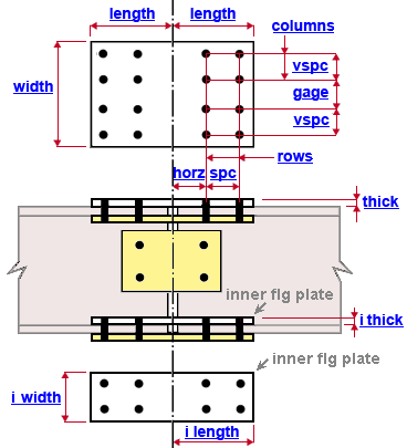 |
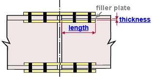
" ( values of 0 if fill plate not designed ) 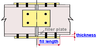 |
||
|
"
|
|||
|
|
||
End connection failure message: Beams have unequal slopes .
Connection Guide: Click here .
As noted above: Values that you enter for "
Moment Flange Plate " connection design locks on one beam are duplicated on the other beam. The two halves of each splice plate are mirror images of each other.
User Defined Connections: Settings that are locked (
) in a user defined connection file will automatically be locked on a member edit window for which that file is the " Input connection type ." You can, if you so choose, manually lock additional settings on the member edit window, and your changes will be retained, through multiple processes, so long as you do not change to a different connection then switch back to the original user defined connection.
Beam Edit: To change a setting, first set it to locked (
). Related settings that are unlocked (
) may be updated, and the "
Left/Right end limit state " calculations will be updated. Settings that are locked (
) will not be changed by connection design , even if doing so might prevent a connection failure.
Connection design locks :
| Locks not dimensioned or called out on the drawing are marked ( not depicted ). All locks that are applied to the one beam are copied to the opposing beam that shares moment web flange plates. |
![]() Moment Flange Plate
Moment Flange Plate
Top and bottom moment flange plates
Plate length on this member ( length ): The distance (parallel with the work lines of the beams) from the beam work point to the farthest edge of the half of the plate that is on the beam you are editing (see the example ). This distance is horizontal if the beams do not slope. If " Plate length on this member " is unlocked (
), changing the number of " Rows " or " Horizontal spacing " or " Horizontal to holes " also changes the " Plate length on this member ." The " Plate length on this member " that you enter for this beam plus the " Plate length on this member " for the other beam that is being spliced add up to the total length of the top and bottom moment flange plates.
Plate width ( width ): The distance (perpendicular to the work lines of the beams) between the two edges of the moment flange plate that are parallel with the work lines of the beams (see example ). If " Plate width " is unlocked (
), changing the " Columns " or " Vertical spacing " or " Gage " also changes the " Plate width ." The " Plate width " entered here is also the plate width of the fill plate if one is designed.
Plate thickness ( thick ): The " Material thickness " of the moment flange plate (see example ).
Top and bottom inner flange plates
Plate length on this member ( i_length ): The distance (parallel with the work lines of the beams) from the beam work point to the farthest edge of the half of the plate that is on the beam you are editing (see example ). The length may be different on this member as opposed to the other member. The plate length on this member plus the plate length on the other member are, together, the actual plate length of each of the four inner flange plates.
Plate width ( i_width ): The distance (perpendicular to the work lines of the beams) between the two edges of the inner flange plate that are parallel with the work lines of the beams (see example ). All four inner flange plates are this same width.
Plate thickness ( i_thick ): The " Material thickness " of the inner flange plates (see example ). All four inner flange plates are this same thickness.
Offset from beam centerline ( not depicted ): The distance (perpendicular to the work lines of the beams) from the interior edge of any one inner flange plate to the centerline of the beam. All four inner flange plates are offset this distance from the centerlines of the two beams being spliced.
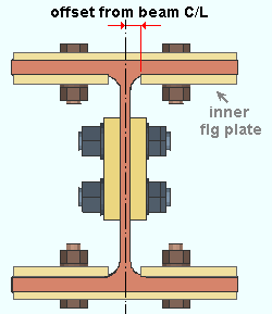
In this example, the inner flange plates (all 4 of them) are offset the k1 distance from the centerline of the beam. The work lines of the two beams being spliced are colinear and on the same plane.
Bolts on this member ( values entered apply to BOTH beams, not just this beam )
Bolt diameter ( not depicted ): You can either type in any diameter (inches or mm), or you can select a bolt diameter from the combo box (
). The diameters that are listed in the combo box come from Home > Project Settings > Job > Bolt Settings > the " Available bolts " list. The bolt diameter entered here together with the " Hole type " determine the diameter of holes the bolts go into.
Hole type ( not depicted ): Standard round or Short slot or Oversized or Long slot or User slot #1 or User slot #2 . The hole type selected here, together with the " Bolt diameter " entered above, set the hole diameter.

Rows: The number of rows of holes on the half of the moment flange plate that bolts to the flange of the beam you are editing. This is half of the total number of rows that are on the entire flange plate. Bolt row spacing runs parallel with the work lines of the beams. Since the flange plate is symmetrical, changing the number of " Rows " on one beam results in the same number of " Rows " being applied to the opposing beam. In the example above, the number of rows on the near side of the top moment flange plate is ' 2 '. If " Plate length on this member " is unlocked (
), changing the number of " Rows " also changes the " Plate length on this member ."
Row spacing ( spc ): The distance (center to center) between any adjacent rows of holes on the moment flange plate (see example ). If " Plate length on this member " is unlocked (
), changing the " Horizontal spacing " also changes the " Plate length on this member ."
Distance to 1st row ( horz ): The distance (parallel with the work lines of the beams) from this beam's work point to the center of the nearest row of holes on the half of the plate that is on the beam you are editing (see example ). The value you enter here will also be applies as the " Horizontal to holes " on the opposing beam being spliced. This dimension is horizontal only if the beams being spliced are horizontal. If " Plate length on this member " is unlocked (
), changing the " Horizontal to holes " also changes the " Plate length on this member ."
Columns: Half of the total number of columns of holes on the flange plate. In the example above, this number is ' 2 ', while the total number of columns of holes is ' 4 '. If " Plate width " is unlocked (
), changing the number of " Columns " also changes the " Plate width ."
Gage: The distance (center to center) between the two columns of holes that are closest to the work line of the beam you are editing (see example ). If " Plate width " is unlocked (
), changing the " Gage " also changes the " Plate width ."
Column spacing ( vspc ): The distance (center to center) between any adjacent columns of holes on the moment flange plate (see example ). If " Plate width " is unlocked (
), changing the " Vertical spacing " also changes the " Plate width ."
![]() Flange Filler Plate
Flange Filler Plate
| Note: If the two beams being spliced are equally deep, a " |
Fill plate dimensions
Length ( fill length ): The distance (parallel with the work lines of the beams) between the two edges of the fill plate that are parallel with the depth of the beams.
Plate thickness ( thickness ): The " Material thickness " of the fill plate.
Other filler plate dimensions are controlled by " Moment Flange Plate " locks: The " Plate width " of the moment flange plate sets the fill plate width. The hole pattern in the moment flange plate also sets the hole pattern in the fill plate.
![]() Inner Flange Filler Plate
Inner Flange Filler Plate
| Note: If the two beams being spliced have equally thick flanges, an " |
Top inner filler plates
Plate length on this member ( length ): The distance (parallel with the work lines of the beams) from the beam work point to the farthest edge of the half of the inner flange filler plate that is on the beam you are editing (see example ). The length may be different on this member as opposed to the other member. Both the NS and FS inner flange plates will extend this same length along this member from the splice connection centerline.
Plate width ( not depicted ): The distance (perpendicular to the work lines of the beams) between the two edges of the inner flange filler plate that are parallel with the work lines of the beams (see example ). Both the NS and FS top inner flange filler plates are this same width.
Plate thickness ( thickness ): The " Material thickness " of the top (NS and FS) inner flange plates (see example ).
Offset from beam centerline ( not depicted ): The distance (perpendicular to the work lines of the beams) from the interior edge of any one inner flange plate to the centerline of the beam. Both of the top inner flange filler plates are offset this distance from the centerlines of the two beams being spliced.
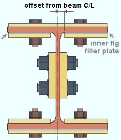
In this example, the top inner flange filler plates (both of them) are offset the k1 distance from the centerline of the beam. The work lines of the two beams being spliced are colinear and on the same plane.
Bottom inner filler plates
Plate length on this member ( not depicted ): Same as " Plate length on this member " under " Inner Flange Filler Plates ," except that this applies to the bottom inner filler plates.
Plate width ( not depicted ): Same as " Plate width " under " Inner Flange Filler Plates ," except that this applies to the bottom inner filler plates.
Plate thickness ( not depicted ): Same as " Plate thickness " under " Inner Flange Filler Plates ," except that this applies to the bottom inner filler plates.
Offset from beam centerline ( not depicted ): Same as " Offset from beam centerline " under " Inner Flange Filler Plates ," except that this applies to the bottom inner filler plates.
