 Continuous Footing ( Modeling > F2 >
  Concrete > " Continuous Footing" )
Tool summary :
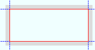
The Continuous Footing Edit window :
|
|
To open this window :
- With the Default filter selected, double-click a continuous footing member.
- Add a continuous footing .
On this page :
Also see :
- Modeling (where a continuous footing can be added or edited)
- Continuous footing (definition)
- Concrete Setup > Continuous Footing Templates (lists available continuous footing templates)
- Continuous Footing Template Editor (setup options for adding/editing/reviewing an individual template)
- Move Layout Nodes (another way to edit the layout )
To add a continuous footing layout :
|
Before adding a continuous footing, you should confirm that the template that you want to use for the continuous footing is listed in Concrete Setup > Continuous Footing Templates . The template sets, for example, whether the concrete profile of the continuous footing is rectangular or an irregular shape. It also defines the continuous footing's rebar system.
A continuous footing can be added in Modeling by pressing F2 to open the Member Type Selection window, then double-clicking " Continuous Footing ."
Continuous footings are typically laid out in a plan view . Using the point locator INCL to locate the continuous footing work points puts the top of the continuous footing at the elevation of the plan view. If you want to use point locator options other than INCL , consider employing the Z filter toggle (
) to ensure that all located points snap to the elevation of the plan view. It is not required that the elevation of all points be at the elevation of the plan view, but you may prefer that they be at that elevation.
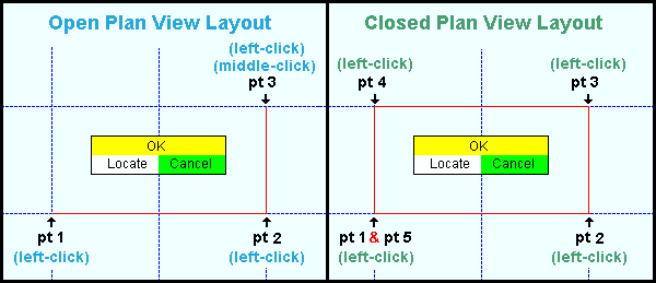
Continuous footings are added as a layout.
To achieve an open layout, you need to middle-click ( OK ) after you left-click ( Locate ) the final point.
A closed layout is achieved when you left-click ( Locate ) the final point at the same location as the 1st point. For both of types of layout, the first point you locate establishes the left end of the layout. Common practice is to lay out points counterclockwise.
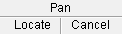
After you have located points as described above, the Continuous Footing Edit window opens. Note that this window includes settings for all of the continuous footing members that you laid out. Be aware that if you press " Cancel " on this window, you will end this continuous footing layout operation without adding any members.
Before you press " OK " to close this window, you must enter a " Template " that defines the profile and rebar system for the continuous footing.
After you press " OK " to close the Continuous Footing Edit window when adding such a layout for the first time, you need to right-click ( Cancel ) in order to end the layout operation.

mouse bindings A continuous footing can have footing steps. The procedure for adding such a footing is similar to the procedures described above, except that is usually easier to add them in an elevation view when a footing step is required.
Using the point locator INCL to locate the continuous footing work points puts the top of the continuous footing at the elevation of the work points. The first point you locate establishes the left end of the layout. Common practice is to lay out points from left to right, and to achieve an open layout by not locating the final point at the same location as the 1st point. In order to model a footing step, the work points of at least one segment must have a Z location directly above or below work points of the preceding segment. However, neither of these workpoints can define the left or right end of the footing. To add the final point, middle-click ( OK ) after you left-click ( Locate ).
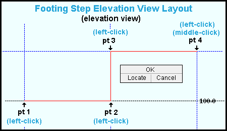
After you have located points as described above, the Continuous Footing Edit window opens. Note that this window includes settings for all of the continuous footing segments that you laid out. Be aware that if you press " Cancel " on this window, you will end this continuous footing layout operation without adding any members.
Before you press " OK " to close this window, you must enter a " Template " that defines the profile and rebar system for the continuous footing. In addition, you must enter a " Step template " that defines the profile and rebar system for the footing step.
After you press " OK " to close the Continuous Footing Edit window when adding such a layout for the first time, you need to right-click ( Cancel ) in order to end the layout operation.
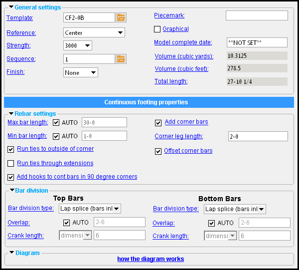
| Continuous footing properties |
------  General settings ------
Reference: Center or Interior or Exterior . The choices you have for " Reference " behave differently depending on whether you laid out points for the continuous footing counterclockwise or clockwise. Changing the " Reference " of a continuous footing does not reposition the member line of the continuous footing. That is, it does not reposition the representation of the continuous footing as shown in stick form . It repositions the concrete with respect to that stick form member line. The member line of the continuous footing always remains defined by its original layout points .
If points were laid out counterclockwise:
|
||||
| ' Center ' centers the concrete profile defined in the " Template " with respect to the continuous footing's member line. ' Interior ' places the continuous footing's concrete profile to the interior of the continuous footing's member line. ' Exterior ' places the continuous footing's profile to the exterior of the continuous footing's member line. |
If points were laid out clockwise:
|
||||
| ' Center ' centers the profile defined in the " Template " with respect the continuous footing's member line. ' Interior ' places continuous footing's profile exterior to its member line. ' Exterior ' places the continuous footing's profile interior to its member line. |
Changing the " Reference " results in the " Volume (cubic yards) " " Volume (cubic feet) " and " Total length " being recalculated for this continuous footing after you press " OK ."
------ Rebar settings ------
Max bar length: ![]() AUTO or
AUTO or ![]() AUTO .
AUTO .
'
'
AUTO (not checked) ' lets you enter a distance in the primary dimension " Units " or other units .
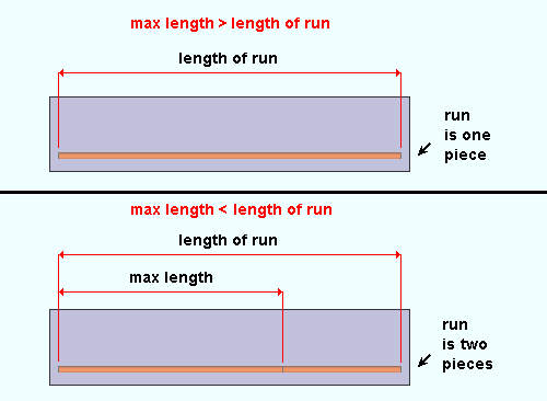
Max length >= length of run: If the " Max bar length " that is entered is greater than or equal to the length of a rebar run in a particular continuous footing segment, the rebar run will consist of a single rebar that is the required length. That required length is based on the distance between the two end points of a continuous footing segment.
Max length < length of run: If the " Max bar length " that is entered is less than the length of the rebar run in a particular continuous footing segment, the rebar run is broken two or more rebar lengths, the first of which is (or are) the " Max bar length ."
Example: " Max bar length " results in each rebar run in the concrete beam being divided into three rebar segments. The first two segments are the " Max bar length ." The third segment is the length that is required to complete the run.
Min bar length: ![]() AUTO or
AUTO or ![]() AUTO .
AUTO .
'
'
Lap length: ![]() AUTO or
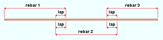
AUTO or ![]() AUTO . This applies when the runs of longitudinal rebar for one or more continuous footing segments have been dividend into multiple rebar lengths to accommodate the " Max bar length ." A lap splice is a common way of splicing two reinforcing bars. Lap splices that are within the same rebar run are modeled as a material clash between the two lengths of rebar that are being spliced. The length that the rebar clashes in the model is the " Lap length " that has been entered.
AUTO . This applies when the runs of longitudinal rebar for one or more continuous footing segments have been dividend into multiple rebar lengths to accommodate the " Max bar length ." A lap splice is a common way of splicing two reinforcing bars. Lap splices that are within the same rebar run are modeled as a material clash between the two lengths of rebar that are being spliced. The length that the rebar clashes in the model is the " Lap length " that has been entered.
'
'
|
| Entering an appropriate " Lap length " ensures that sufficient lengths of rebar are ordered to achieve a lap splice. As shown in this diagram, a lap splice that is within the same rebar run is modeled as a material clash. |
Add corner bars: ![]() or
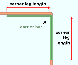
or ![]() . A corner bar is created to splice rebar at the intersection of two segments of the grade beam.
. A corner bar is created to splice rebar at the intersection of two segments of the grade beam.
If this box is checked (
If the box is not checked (
Corner leg length: A distance in the primary dimension " Units " or other units . This option applies when " Add corner bars " is checked ( ![]() ). Each leg of the corner bar will be this distance long.
). Each leg of the corner bar will be this distance long.
|
The option to " |
Offset corner bars: ![]() or
or ![]() . This option applies when " Add corner bars " is checked (
. This option applies when " Add corner bars " is checked ( ![]() ).
).
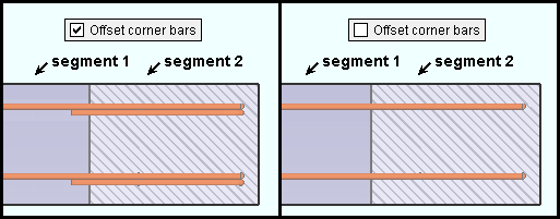
If this box is checked (
If the box is not checked (
Add hooks to cont. bars in 90 degree corners: ![]() or
or ![]() . This applies when two segments of the continuous footing intersect at 90 degrees.
. This applies when two segments of the continuous footing intersect at 90 degrees.
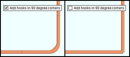
If this box is checked (
If the box is not checked (
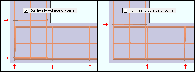
Run ties to outside of corner: ![]() or
or ![]() . This applies when two segments of the continuous footing intersect.
. This applies when two segments of the continuous footing intersect.
|
|
The arrows ( |
If this box is checked (
If the box is not checked (
Run ties through extensions: ![]() or
or ![]() . This applies when ties have been defined in the selected " Template " and "
. This applies when ties have been defined in the selected " Template " and " ![]() Extend dowels " is turned on in order to extend rebar beyond the left- and/or right-end continuous footing segment.
Extend dowels " is turned on in order to extend rebar beyond the left- and/or right-end continuous footing segment.
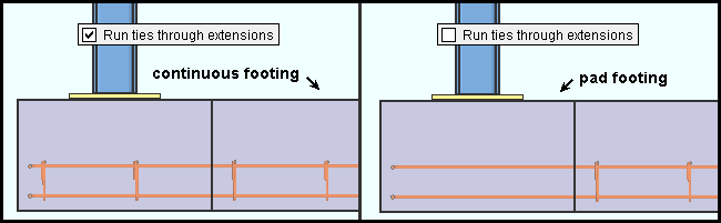
If this box is checked (
If the box is not checked (
Also see: Extend dowels
------ Bar division ------
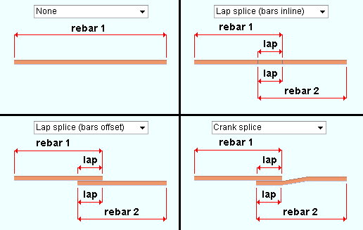
Bar division: None or Lap splice (bars inline) or Lap splice (bars offset) or Crank splice . These options determine if or how bars are spliced.
|
| Bar division options affect the length of rebar shape material. |
' None ' prevents splices from being modeled. The rebar is modeled as a single length.
' Lap splice (bars inline) ' models splices that accommodate the " Max bar length " and the " Overlap "; however, the splices are within the same rebar run and are modeled as clashing material.
' Lap splice (bars offset) ' models splices that accommodate the " Max bar length " and the " Overlap ". The bars are offset so that their material does not clash.
' Crank splice ' models splices that accommodate the " Max bar length " and the " Overlap ". The bars are within the same rebar run, but cranks are provided that conform to the " Crank length " options to prevent the bars from clashing.
Overlap: ![]() AUTO or
AUTO or ![]() AUTO . This applies when the runs of horizontal rebar have been divided into multiple rebar lengths to accommodate the " Max bar length ." A lap splice is a common way of splicing two reinforcing bars. Lap splices that are within the same rebar run are modeled as a material clash between the two lengths of rebar that are being spliced. The length that the rebar clashes in the model is the " Overlap " that has been entered.
AUTO . This applies when the runs of horizontal rebar have been divided into multiple rebar lengths to accommodate the " Max bar length ." A lap splice is a common way of splicing two reinforcing bars. Lap splices that are within the same rebar run are modeled as a material clash between the two lengths of rebar that are being spliced. The length that the rebar clashes in the model is the " Overlap " that has been entered.
'
'
|
|
| Entering an appropriate " Overlap " ensures that sufficient lengths of rebar are ordered to achieve a lap splice. As shown in this diagram, a lap splice that is within the same rebar run is modeled as a material clash. |
Crank length: ratio or dimension . This option applies when " Bar division type " is ' Crank splice '.
' ratio ' specifies the ratio (expressed as a decimal number) of the crank length to bar size; that is, the crank length divided by the bar size. It follows that if you multiply the ratio by the bar size, you can calculate the resulting crank length:
Example using imperial units :
ratio = ' 6.0 '
bar size = #6 (i.e. 3/4", or 0.75 )
crank length = CC ÷ 0.75 = 6.0
C = 6.0 × 0.75
C = 4.5 , or 4 1/2"Example using metric units :
ratio = ' 6.0 '
bar size = #19 (i.e. 19 mm)
crank length = CC ÷ 19 = 6.0
C = 6.0 × 19
C = 114 mm' dimension ' specifies the crank length as a distance in the primary dimension " Units " or other units . This option allows the crank length to be entered directly.
 |
| Tip: You can also change the coordinates by using the Move Layout Nodes tool in the model. |
Radius: A distance (in the primary dimension " Units " or other units ) that defines the amount of corner rounding that takes place.
" Radius " is the radius of a circle. Two lines that are tangent to that circle meet at the located point. The arc of the rounded corner ends at the points of tangency of these two lines. 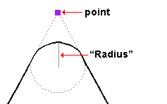
A " Radius " of ' 0 ' designates a sharp corner with no corner rounding.
Increasing the size of the " Radius " moves the edge of the rounded corner back from the corner point. This is because the " Radius " defines a circle that is tangent to both lines to the corner point. The arc of the rounded corner begins and ends at the tangent points.
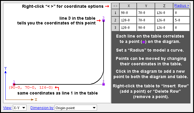
You can set a different " Radius " for each corner. Clicking on the upper-right corner of the table (" Radius > ") lets you set the radius for each point to be the same value.
' X-Y ' shows a plan view of the layout points . If all of the " Z-axis " values shown in the diagram's table are the same, this view best represents the relative spacing of the layout points.
' X-Z ' shows an elevation view of the layout points in a flat, X-Z plane that is at right angles to (orthogonal to) the Y global axis .
' Y-Z ' shows a elevation view of the layout points in a flat, Y-Z plane that is orthogonal to the X global axis.
Dimension by: Length and angle or Previous point or Origin point . This applies when you hover a point in the diagram with your mouse pointer ( ![]() ), regardless of whether or not you are adding points.
), regardless of whether or not you are adding points.
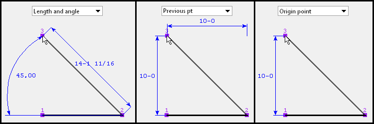
' Length and angle ' shows one or two dimensions and an angle. The dimension(s) are to the point you are hovering. One dimension may be to the previous point, and another dimension may be to the next point. The angle to the point you are hovering may be the included angle between the hovered point and the previous two points. Or it may be the angle between the hovered point and a horizontal or vertical bisector to the previous point.
VIDEO " Dimension by " is set to ' Length and angle ' and the distance and angle between points is entered by the narrator as the first two points are defined. The other points are defined by just clicking instead of typing. ' Previous point ' shows horizontal and/or vertical dimensions between the point you are hovering and the previous point in the diagram. Dimensions of zero will not be shown.
' Origin point ' shows horizontal and/or vertical dimensions from the origin point (point 1) to the point you are hovering. Dimensions of zero will not be shown.
Adding points: You can click a line in the diagram to add a point. The new point snaps to your mouse pointer until you left-click to locate that point or right-click to cancel. Dimensions are shown as you move your mouse pointer to reposition the snapped-to point. An alternative to clicking in the diagram to add points is to enter the points to the table.
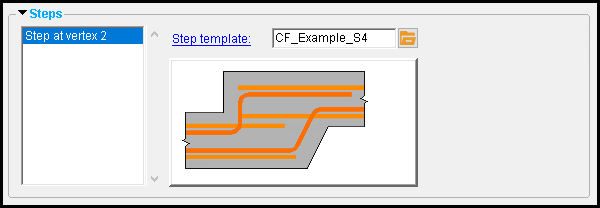
------ Steps ------
Step template: A template file name that has been defined on the Footing Step Templates window. The template defines the steps's concrete profile along with its step bars, nosing bar, and tie zones.
To enter a template, press the "file cabinet" browse button (
) and double-click any template that is listed.
|
|
|
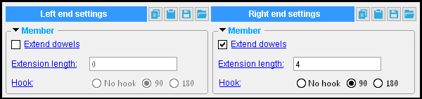
------ Member ------
Extend dowels: ![]() or
or ![]() . This applies when rebar has been defined in the selected " Template ." It affects only the outside end ( left or right ) of the outside segment of the continuous footing.
. This applies when rebar has been defined in the selected " Template ." It affects only the outside end ( left or right ) of the outside segment of the continuous footing.
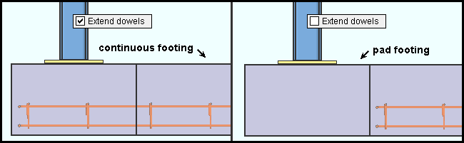
If this box is checked (
If the box is not checked (
Also see: Run ties through extensions
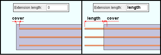
Extension length: A distance (in the primary dimension " Units " or other units ). This option applies when the option to " ![]() Extend dowels " is checked. It affects only the outside end ( left or right ) of the outside segment of the continuous footing.
Extend dowels " is checked. It affects only the outside end ( left or right ) of the outside segment of the continuous footing.
|
| This example demonstrates the result of entering a non-zero " Extension length " for " Left end settings ." That same entry under " Right end settings " would extend the dowels beyond the right end of the right-end continuous footing segment. |
An extension length of ' 0 ' does not extend the longitudinal reinforcement bars (horizontal dowels). The reinforcement bars extend only to the end cover of the continuous footing, which is the same result that you would get if you were to uncheck the box for "
An extension length ' greater than 0 ' extends the reinforcement bars that distance past the end of the continuous footing.
Hook: No hook or 90 or 180 . This option applies when the option to " ![]() Extend dowels " is checked. It affects only the outside end ( left or right ) of the outside segment of the continuous footing.
Extend dowels " is checked. It affects only the outside end ( left or right ) of the outside segment of the continuous footing.
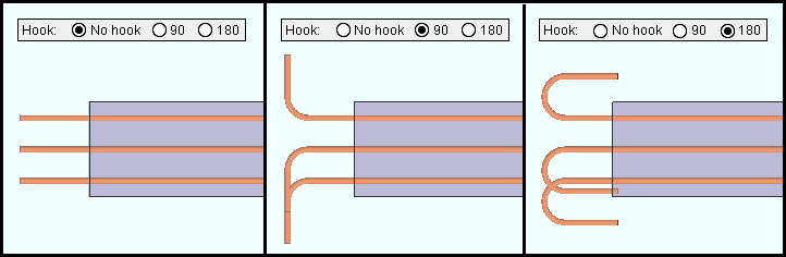
' No hook ' results in a straight rebar end.
' 90 ' results in a 90 degree hook at the end of the rebar.
' 180 ' results in a 180 degree hook at the end of the rebar.

