"  NS/FS Clip Conn1 " & " NS/FS ClipConn2 " connection design locks (4 leaves)
| Horizontal brace gusset clip angles can be designed for a horizontal brace (any material type) to a beam-beam corner in order to field bolt the gusset plate to each beam's web. " |
|
|||
|
"
|
" (" Gusset to clip connection " = ' Welded ') 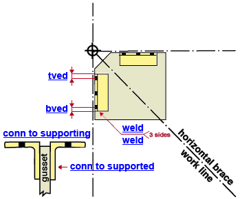 |
||
|
|
||
Connection Guide: Click here for related screen shots.
User Defined Connections: Settings that are locked (
) in a user defined connection file will automatically be locked on a member edit window for which that file is the " Input connection type ." You can, if you so choose, manually lock additional settings on the member edit window, and your changes will be retained, through multiple processes, so long as you do not change to a different connection then switch back to the original user defined connection.
Horizontal Brace Edit: To change a setting, first set it to locked (
) may be updated, and the "
Length & width of the gusset plate:
Width = "
Length = "
Connection design locks :
| Locks not called out or dimensioned on the drawing are marked ( not depicted ). |
![]() NS Clip Conn1 /
NS Clip Conn1 / ![]() FS Clip Conn2
FS Clip Conn2
(horizontal brace to a beam-beam corner, clip angles to the webs of the beams)
|
Clip angle(s) can be on ' Both sides ' or ' Near side ' or ' Far side ' of the gusset plate. You get a leaf for " |
:
Section size ( not depicted ): The angle material to be used for the NS or FS gusset clip angle. For example, ' L3x3x5/16 '. The angle you enter must exist in the local shape file, or validation will not accept your entry. To enter an angle section size, you can type in the section size that you want, or you can press the "file cabinet" browse button (
) and double-click any section that is on the list of available angles in the local shape file . If you are in the "
Long leg to ( not depicted ): Supported or Supporting . This applies when the " Section size " is an angle with unequal legs. If you want the long leg of the angle to fasten to the gusset plate, select ' Supported '. If you want the long leg of the angle to fasten to the supporting beam, select ' Supporting '.
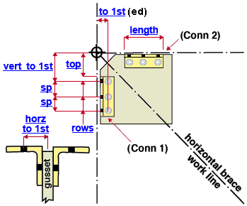
Top of angle ( top ): The distance (parallel with the length of the angle) from the work point of the horizontal brace to the angle's edge that is closest to that work point. A " Top of angle " of ' 0 ' aligns the edge of the angle with the brace's work point. A distance greater than zero moves the angle away from the work point. Changing the " Top of angle " moves the angle only, not the holes in the angle.
Length of angle ( length ): The length of the longest edge of the angle, the edge that runs parallel with the work line of the beam that it field bolts to -- see example . Assuming that this field is unlocked (
Connection to supported (gusset clip angle, NS or FS, leg welded or bolted to the gusset plate) :
When "
Weld size ( weld ): The weld size for shop welding the angle to the gusset plate (see example ). This lockable field appears as a " Connection to supported " option only when the " Gusset to clip connection " is set to ' Welded '. When the " Gusset to clip connection " is set to ' Bolted ', " Weld size " does not apply, and therefore it is not shown as an option.
When the " Gusset to clip connection " is set to ' Bolted ', you get the following " Connection to supported " options for shop bolting the brace to the gusset plate. " Connection to supported " settings can be different than the entries made to " Connection to supporting " fields.
Bolt diameter ( not depicted ): May be different than the " Bolt diameter " in the leg to supporting.
diameter of leg-to-gusset shop bolts 
Hole type ( not depicted ): The setting applied here, for the leg to gusset, may be different than the " Hole type " in the leg to the supporting.
Rows ( not depicted ): The setting applied here, for the leg to gusset, may be a different number than the " Rows " in the leg to supporting.
Vertical to 1st hole ( not depicted ): If, for the " Connection to supported ," you enter a " Vertical to 1st hole " to the "
End connection failure message: Locked vertical to 1st hole value on supported must match .
Vertical hole spacing ( not depicted ): It is permissible to have leg-to-gusset hole spacing that is different than the " Vertical hole spacing " in the leg to supporting.
Top vertical edge distance ( not depicted ): You are permitted to enter a leg-to-gusset top vertical edge distance that is different than the " Top vertical edge distance " in the leg to supporting.
Bottom vertical edge distance ( not depicted ): You are permitted to enter a leg-to-gusset bottom vertical edge distance that is different than the " Bottom vertical edge distance " in the leg to supporting.
Horizontal to 1st hole ( to 1st ): The distance (perpendicular to the length of the angle) from the horizontal brace's work point to the center of the holes in the leg to the gusset plate (see example ). For " NS/FS Conn1 ," this dimension is parallel with the length of the gusset plate. For " NS/FS Conn2 ," the dimension is parallel with the width of the gusset plate. When the " Gusset to clip connection " is set to ' Welded ', " Horizontal to 1st hole " does not apply, and therefore it is not an available option.
Connection to supporting (beam corner gusset clip angle, NS or FS, leg that field bolts to one supporting beam) :
Regardless of whether the " Gusset to clip connection " is set to ' Welded ' or ' Bolted ', the connection to supporting is a field bolted connection with following options:
Bolt diameter ( not depicted ): The diameter of field bolts in the leg to the supporting beam. You can either type in any diameter (inches or mm), or you can select a bolt diameter from the combo box (
). The diameters that are listed in the combo box come from Home > Project Settings > Job > Bolt Settings > the " Available bolts " list.The bolt diameter entered here also determines the diameter of holes the bolts go into.
diameter of OSL field bolts 
Hole type ( not depicted ): Standard round or Short slot or Oversized or Long slot or User slot #1 or User slot #2 . The hole type selected here, together with the " Bolt diameter " entered above, set the diameter of holes for bolting to the angle to the supporting beam.

Rows: The number of rows of bolts in the angle leg to the beam. If the " Length of angle " is unlocked (
Vertical to 1st hole ( to 1st ): The distance (parallel with the length of the angle) from the work point of the horizontal brace to the center of the nearest hole in the leg to the supporting beam (see example ). A " Vertical to 1st hole " of ' 0 ' aligns the first hole in the gusset clip angle with the brace's work point. Entering a larger distance moves the hole group away from the work point. For " NS/FS Conn1 ," this distance is parallel with the width of the gusset plate. For " NS/FS Conn2 ," the distance is parallel with the length of the gusset plate. If you enter a " Vertical to 1st hole " to the "
End connection failure message: Locked vertical to 1st hole value on supporting must match
Vertical hole spacing ( sp ): The distance (center to center) between any two adjacent holes in the same column of holes in either leg of the angle (see example ). Vertical hole spacing runs parallel with the length of the angle. If the " Length of angle " is unlocked (
VIDEO 
Variable hole spacing can be typed to locked " Vertical hole spacing " fields found in leaves named "
Rows Spacing Result 5 3,5,3,3 4 spaces at 3", 5", 3" and 3" 5 3,5,2@3 4 spaces at 3", 5", 3" and 3" 5 3,5,3 4 spaces at 3", 5", 3" and 3"
(the last spacing -- 3 -- is repeated to fill the spaces that are required for the number of rows)5 3,5,3,3,2,3 End connection failure message (see below). End connection failure message: Variable row spacing specifies too many rows
Top vertical edge distance ( tved ): The distance from the "top" edge of the gusset angle to the row of bolts in the leg to the supporting beam that is nearest to that edge. The top edge of the angle is the edge that is nearest to the work point of the horizontal brace.
Bottom vertical edge distance ( bved ): The distance from the farthest-from-the-work-point edge of the angle (its bottom edge) to the nearest-to-that-edge row of bolts in the leg to the supporting beam. The bottom edge of the angle is the edge that is opposite to the top edge that the " Top of angle " is measured to. It is the edge that is farthest from the work point of the horizontal brace.
Horizontal to 1st hole ( horz to 1st ): The distance from the work point (center of gusset plate) to the center of the holes in the gusset angle leg that bolts to the supporting beam. See the example .

