"  Brace Connection To Gusset " connection design locks
| Rod braces are designed when a round bar is entered as the vertical brace " Section size ." |
|
- A different set of locks control the bottom end & top end of the brace.
- Changes you make in the bottom end leaf may automatically update unlocked fields in the top end leaf.
- Setup for rod braces is in " Tension Only Braces " in Member Detailing and Fabricator Options .
- Steel grade setup is in Turnbuckle / Clevis / Pin Grades .
- The " Capacity " (nominal strength) of a clevis and turnbuckle is in Shapes Properties .
- Click here for information about this connection from the Connection Guide.
|
||
| " ( bottom end & top end ) 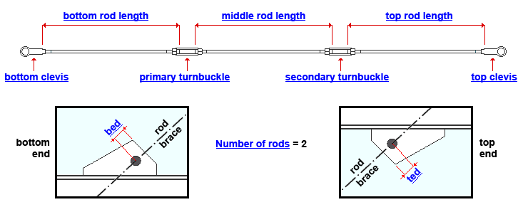 |
||
|
User Defined Connections: Settings that are locked (
) in the user defined connection file will automatically be locked on the member edit window. You can, if you so choose, manually lock additional settings on the member edit window, and your changes will be retained, through multiple processes, so long as you do not change to a different connection then switch back to the original user defined connection.
Vertical Brace Edit: To change a setting, first set it to locked (
). Related settings that are unlocked (
) may be updated, and the "
Left/Right end limit state " calculations will be updated. Settings that are locked (
) will not be changed by connection design , even if doing so might prevent a connection failure.
Connection design locks :
| Locks not dimensioned or called out on the drawing are marked ( not depicted ). |
Bottom end of a round bar vertical brace
Clevis index ( bottom clevis ): The section size of the bottom clevis. You can type in the section size that you want, or you can press the "file cabinet" browse button (
) and double-click any section that is on the list of available clevises in the local shape file . Validation does not let you enter a section that is not available in the local shape file.
End connection failure message: Suitable clevis capacity not found
Clevis pin diameter ( not depicted ): The diameter of the shaft of the pin for the bottom clevis. When this is unlocked (
), connection design selects the " Maximum pin diameter " that is specified for the " Clevis indes " that is selected. Changing the pin diameter can result in a different " Clevis index " being selected, or it may result in the end connection failure message " Clevis/turnbuckle/clevis pin size failure ."
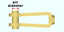
End connection failure message: Clevis pin capacity exceeded
End connection failure message: Clevis pin diameter not within the reqd max/min valuesClevis pin length ( not depicted ): The distance from one end of the clevis pin to its opposite end. The length of the pin includes its head. This applies to the pin for the bottom clevis.
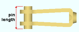
Clevis pin shoulder height ( not depicted ): The distance that the head of the clevis pin extends beyond the shaft of the pin. This applies to the pin for the bottom clevis. This setting is available only if " Pin type " is set to ' Headed ' in Member Detailing and Fabricator Options .
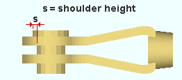
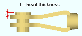
Clevis pin head thickness ( not depicted ): The length of the clevis pin head. This distance is measured along the length of the pin. It applies to the pin for the bottom clevis. This setting is available only if " Pin type " is set to ' Headed ' in Member Detailing and Fabricator Options .
Clevis pin grade ( not depicted ): This applies to the pin for the bottom clevis. The steel grades that you can select in this list box (
) come from Home > Project Settings > Job > Turnbuckle / Clevis / Pin Grades . Connection design uses the Fy and Fu values from that window to determine the strength of the clevis pin. Also see: " Clevis pin grade " in the "
Brace Connection To Gusset " leaf for the top end sets the clevis pin grade on that end.
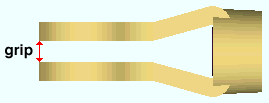
Clevis grip ( not depicted ): The distance between the prongs of the bottom clevis.
Clevis thread ( not depicted ): ' Right ' or ' Left ' This applies to the bottom clevis. If, for example, you lock (
) this field and change from ' Righ t ' to ' Left ' , the " Thread type " of the round bar end that screws into this clevis will be switched to ' Left handed '. and, if the " Turnbuckle thread " (bottom) is unlocked (
), it will be switched to ' Right handed ' and the opposite end of that same round bar will be switched to ' Right handed ' to match the bottom turnbuckle.
Turnbuckle index ( primary turnbuckle ): The section size of the primary (bottom) turnbuckle. If a secondary turnbuckle is designed, due to the " Number of rods " being set to ' 2 ', this is also the section size of the secondary (top) turnbuckle. You can type in the section size that you want, or you can press the "file cabinet" browse button (
) and double-click any section that is on the list of available turnbuckles in the local shape file . Validation does not let you enter a section that is not available in the local shape file.
End connection failure message: Suitable turnbuckle size not found
End connection failure message: Suitable turnbuckle capacity not foundTurnbuckle thread ( not depicted ): ' Right ' or ' Left '. This is the thread type for the bottom end of the bottom turnbuckle. Connection design will automatically set the " Thread type " of the round bar end that screws into this end of the turnbuckle to match the choice made here. Also see : The thread type for the top end of the bottom turnbuckle is set using " Turnbuckle thread " in the "
Brace Connection To Gusset " leaf for the top end.
Rod length ( bottom rod length ): The distance between the two ends of the round bar material that is the bottom rod. If you change this length, the top end " Rod length " will automatically be updated (if it is unlocked) along with the " Middle rod length " (if it is unlocked and if there is a middle rod). See the example .
Thread length ( not depicted ): This applies to each end of the bottom, top and, if applicable, middle rod. It is the distance from each of those ends to where you want the threaded area to end. The thread length and thread type (handedness) are dimensioned and annotated on the submaterial detail . Fabricator Setup : " Length of rod brace thread " under " Tension Only Braces " in Member Detailing Settings .
tl = thread length

How Modeling represents the threaded area of a round bar displayed in solid opaque form. Gusset edge distance along brace ( bed ): The distance from the point of intersection between the gusset plate and the brace to the center of the hole in the gusset plate. This applies to the gusset plate for bottom end of the brace. See the example .
Top end of a round bar vertical brace
Clevis index ( top clevis ): The section size of the bottom clevis. You can type in the section size that you want, or you can press the "file cabinet" browse button (
) and double-click any section that is on the list of available clevises in the local shape file . Validation does not let you enter a section that is not available in the local shape file.
Clevis pin diameter ( not depicted ): Same as the " Clevis pin diameter " for the bottom clevis, except that this applies to the top clevis.
Clevis pin length ( not depicted ): Same as the " Clevis pin length " for the bottom clevis, except that this applies to the top clevis.
Clevis pin shoulder height ( not depicted ): Same as the " Clevis pin shoulder height " for the bottom clevis, except that this applies to the top clevis.
Clevis pin head thickness ( not depicted ): Same as the " Clevis pin head thickness " for the bottom clevis, except that this applies to the top clevis.
Clevis pin grade ( not depicted ): Same as the " Clevis pin grade " for the bottom clevis, except that this applies to the top clevis.
Clevis grip ( not depicted ): Same as the " Clevis grip " for the bottom clevis, except that this applies to the top clevis.
Clevis thread ( not depicted ): Same as the " Clevis thread " for the bottom clevis, except that this applies to the top clevis.
Turnbuckle thread ( not depicted ): ' Right ' or ' Left '. This is the thread type for the top end of the bottom turnbuckle. Connection design will automatically set the " Thread type " of the round bar end that screws into this end of the turnbuckle to match the choice made here. Also see : The thread type for the bottom end of the bottom turnbuckle is set using " Turnbuckle thread " in the "
Brace Connection To Gusset " leaf for the bottom end.
Number of rods: ' 1 ' or ' 2 '. This is the number of rods in the top end of the rod brace. That is to say, it is the number of rods that are above the bottom turnbuckle. If this number is ' 2 ', then an additional turnbuckle (a secondary turnbuckle) is needed, and you can specify a " Secondary turnbuckle thread " that applies to both ends of that turnbuckle.
Rod length ( top rod length ): The distance between the two ends of the top rod. If you change this length and the bottom end " Rod length " is locked, the " Middle rod length " will automatically be updated (if it is unlocked). See the example .
Middle rod length: The distance between the two ends of the middle rod. This applies when the " Number of rods " is ' 2 '. A middle rod will not exist when the " Number of rods " on the top end of the brace is ' 1 '.
Secondary turnbuckle thread ( secondary turnbuckle ): This sets the thread type for both ends of secondary turnbuckle to be ' Right ' or ' Left '. A secondary turnbuckle is generated when the " Number of rods " is ' 2 '. This secondary turnbuckle will have the same " Turnbuckle index " as the primary turnbuckle. The secondary turnbuckle is the top turnbuckle. The appropriate end of each of the two rods that screw into this turnbuckle will automatically be designed to have threads that matches the choice you make here.
Gusset edge distance along brace ( ted ): The distance from the point of intersection between the gusset plate and the brace to the center of the hole in the gusset plate. This applies to the gusset plate for top end of the brace. See the example .


